Glass working apparatus and glass working method using the same

Inactive Publication Date: 2009-07-23
GRAIN ELECTRONICS
View PDF4 Cites 2 Cited by
  • Summary
  • Abstract
  • Description
  • Claims
  • Application Information

AI Technical Summary

Benefits of technology

[0008]It is one objective of the present invention to provide a glass working apparatu

Problems solved by technology

However, the application of these conventional devices has some drawbacks on processing speed, cost, appearance or posterior process.
For example, when a mechanical drill is used and rotated by a driving device to cut a glass workpiece, the periphery wall of the cutting hole tends to crack or, worstly, the whole glass workpiece may crack as the drill is lowered vertically to touch and drill the top surface of the glass workpiece.
Theref

Method used


Image

  • Glass working apparatus and glass working method using the same
  • Glass working apparatus and glass working method using the same
  • Glass working apparatus and glass working method using the same

Examples


Example

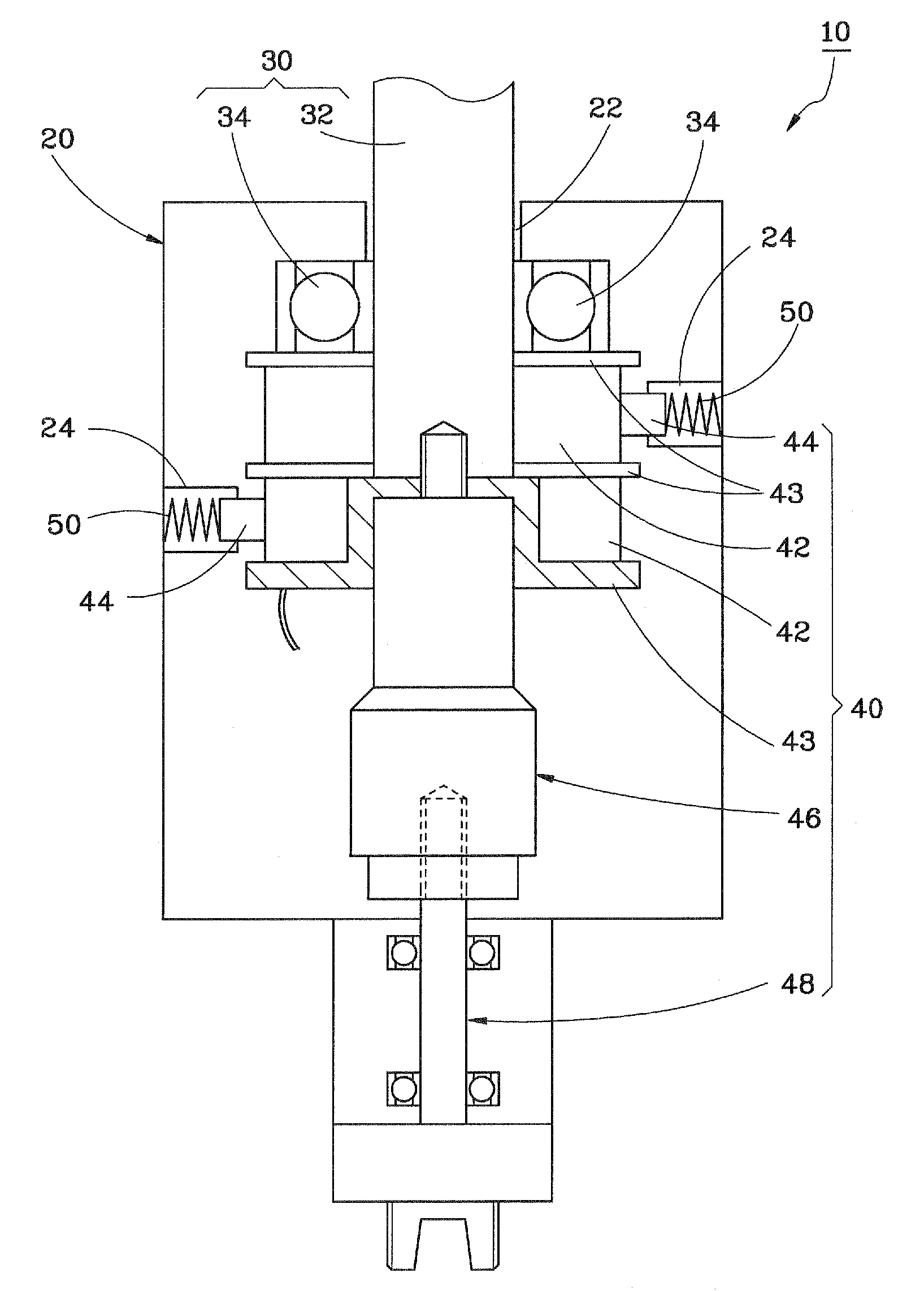
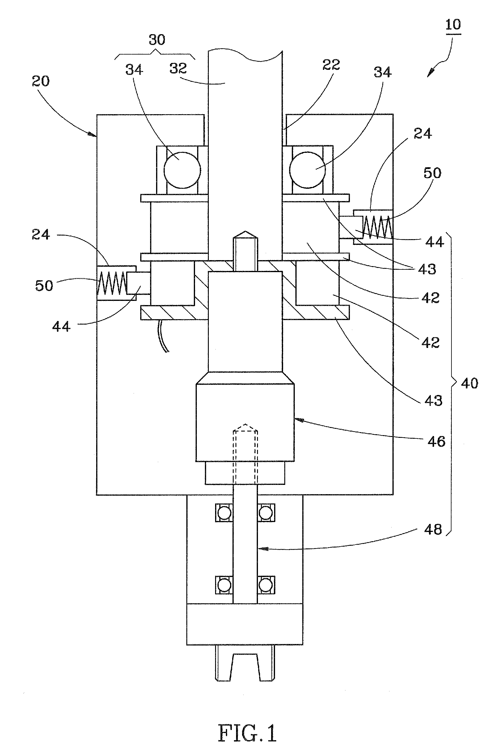
[0021]As shown in FIG. 1, a glass working apparatus 10 in accordance with a preferred embodiment of the present invention comprises a casing 20, a rotating mechanism 30, and an oscillating unit 40.

[0022]The casing 20 has an axle hole 22, and two receiving holes 24 extending from two opposite sides of the periphery toward the inside of the casing 20.

[0023]The rotating mechanism 30 comprises a plurality of axle bearings 34 mounted inside the casing 20 around the axle hole 22, and a shaft 32 inserted through into the axle hole 22 and supported in the axle bearings 34 for free rotation relative to the casing 20.

[0024]The oscillating unit 40 comprises two electrically conductive rings 42, three electrically insulative boards 43 made of Bakelite, two electrically conductive strips 44, an ultrasonic oscillator 46 and a connector 48. As shown in FIG. 1, the electrically conductive rings 42, the electrically insulative boards 43, the ultrasonic oscillator 46 and the connector 48 are fastened...


PUM

PropertyMeasurementUnit
Electrical conductivityaaaaaaaaaa
Circumferenceaaaaaaaaaa

Abstract

A glass working apparatus a casing, in which a rotating mechanism and an oscillating unit are installed. The rotating mechanism has a shaft rotatably mounted in the casing. The oscillating unit is connected with the shaft such that the oscillating unit is rotatable with the shaft. A glass cutting tool is connected to the oscillating unit, such that the glass cutting tool can be driven to rotate by the rotating mechanism through the oscillating unit and/or driven to oscillate by the oscillating unit for working on a glass workpiece.

Description

BACKGROUND OF THE INVENTION[0001]1. Field of the Invention[0002]The present invention relates generally to a glass working apparatus and more particularly, to a glass working apparatus that can process the workpiece efficiently. The present invention also concerns a glass working method adopting the aforesaid apparatus.[0003]2. Description of the Related Art[0004]In glass industry, the quality and efficiency of the glass panel processing are always needed to be concerned and improved. For processing a circular hole, a sand blasting device, mechanical drill or water knife may be used. However, the application of these conventional devices has some drawbacks on processing speed, cost, appearance or posterior process. For example, when a mechanical drill is used and rotated by a driving device to cut a glass workpiece, the periphery wall of the cutting hole tends to crack or, worstly, the whole glass workpiece may crack as the drill is lowered vertically to touch and drill the top surf...

Claims


Application Information

Patent Timeline
IPC IPC(8): B23B47/34
CPCB23B37/00B23B2226/31Y10T408/23B28D1/146B23B2226/45
Inventor LIAO, LU-CHIA
Owner GRAIN ELECTRONICS
Why Eureka
Try Eureka