Light source apparatus

a technology of light source and light source body, which is applied in the field of light source apparatus, can solve the problems of frequent bulb failure, difficult wiring and connection in the handle, time-consuming and therefore costly, etc., and achieve the effect of reducing opportunity and improving ease of sterilisation of the laryngoscope body

Inactive Publication Date: 2009-07-23
DUNLOP COLIN
View PDF23 Cites 25 Cited by
  • Summary
  • Abstract
  • Description
  • Claims
  • Application Information

AI Technical Summary

Benefits of technology

[0016]In the embodiment where the light source comprises an LED, and the switch, light source and contacts are mounted in a sealed mounting, the arrangement has the advantage that the light source lasts a long time (LEDs have a relatively long lifetime) and, because the majority of parts of the arrangement are sealed, the arrangement is resistant to damage from the environment. In an embodiment, the entire assembly fits within a laryngoscope handle. The assembly can therefore be removed if it fails and replaced with a replacement assembly. Advantageously, in an embodiment, the entire sealed “assembly” can be manufactured relatively inexpensively.
[0024]In an embodiment, the sealed mounting comprises plastics arranged to “pot” the light source, electrical circuit and switch. This has the advantage that these light apparatus components are sealed from the environment.
[0026]In an embodiment, the light source is activated by a magnetically operated reed switch. The switch is embedded within the device and no parts of the switch protrude from the laryngoscope body. The absence of switching components protruding from the laryngoscope body improves ease of sterilisation of the laryngoscope body and reduces opportunity for bacteria to become harboured in cracks or crevices in the laryngoscope body.

Problems solved by technology

Installing wiring and connections in handles is difficult, time consuming and therefore costly.
Conventional light bulbs placed in the blade suffer problems with contact caused by moisture in use, and often fail.
These requirements limit the life of an incandescent element, resulting in frequent bulb failure.
Conventional filament bulbs being hot to touch can also burn mucosa.
In this alternative, it can be difficult to obtain access to the bulb in the handle to change the bulb.
In addition, in both the blade mounted and handle mounted bulb variations, the incandescent light bulb is not sealed, the switch is not sealed and there are therefore difficulties in sterilising either the blade or the handle or otherwise exposing the handle to fluid as it can affect the light source and electrical circuit powering the light source.

Method used


Image

  • Light source apparatus
  • Light source apparatus
  • Light source apparatus

Examples


Embodiment Construction

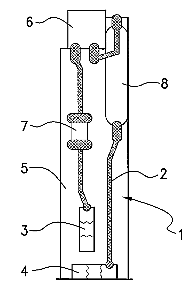
[0036]Referring to the Figures, a light source apparatus in accordance with an embodiment of the present invention comprises an electrical circuit generally designated by reference numeral 1, and in this example being in the form of tracks 2 and contacts 3, 4 mounted on a printed circuit (PCB) 5. It also includes a light source 6, in this example being a light emitting diode (LED) 6. A remotely operable switch, in this example being a magnetically operable reed switch 8, is also included.

[0037]In this embodiment, a resistor 7 is included in the electrical circuit.

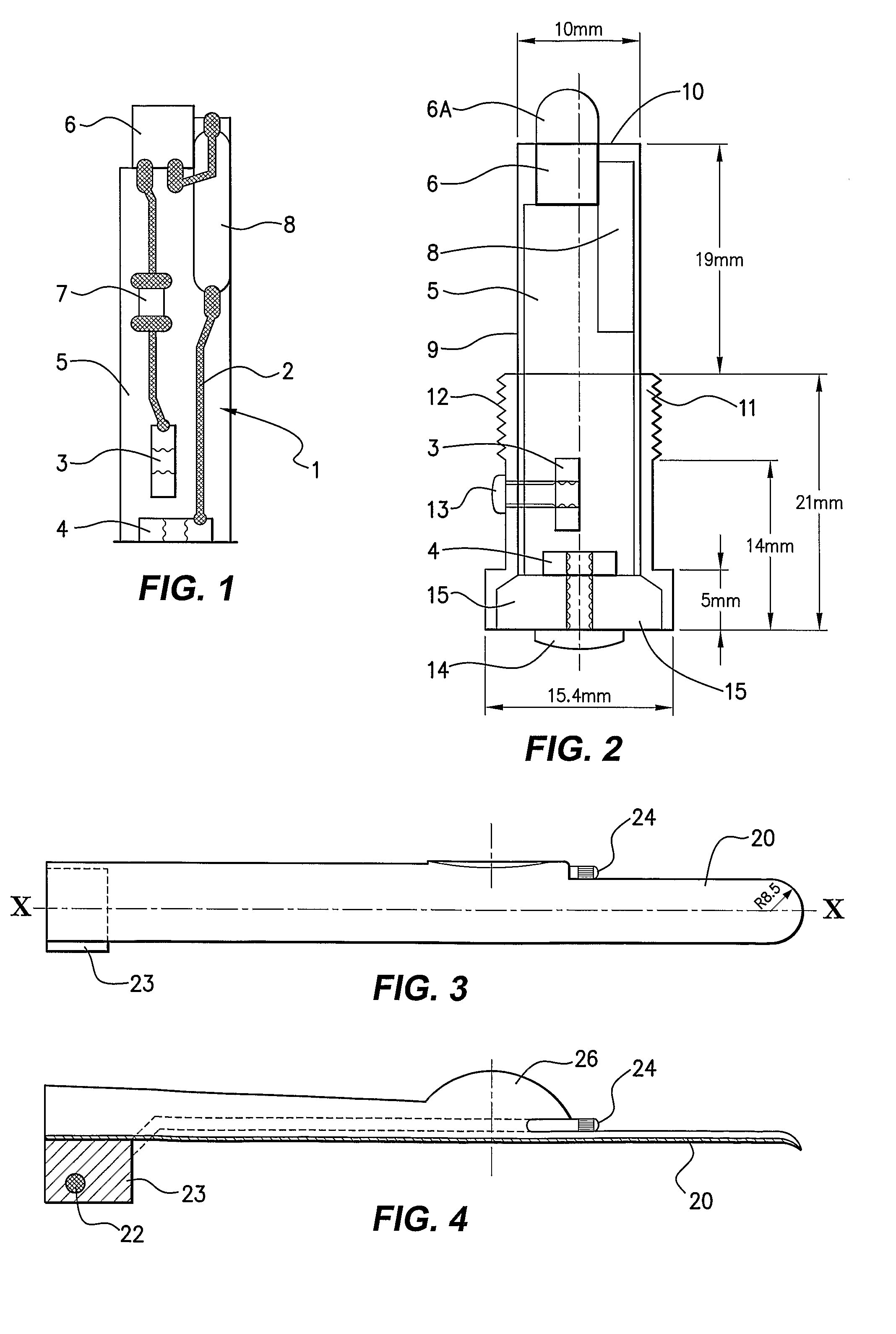
[0038]The PCB 5 illustrated in FIG. 1 is mounted within a sealed mounting, in this embodiment being a resin potted cylinder 9 that permits passage of light from the LED. The potted polyester cylinder 9 seals the components from the environment. Referring to FIG. 2, the LED 6 is ground down (6A) so that its top surface is flush with the top surface 10 of the potted cylinder 9.

[0039]The potted cylinder 9 is seated within a cy...


PUM


Abstract

The present invention relates to a light source apparatus for a laryngoscope. The light source apparatus is remotely operated. In an embodiment, it comprises a magnetically operated reed switch. A co-operating magnet in the laryngoscope blade actuates the reed switch when the blade is brought into proximity with the light source apparatus mounted in the laryngoscope handle.

Description

FIELD OF THE INVENTION[0001]The present invention relates to a lighting apparatus and, particularly, but not exclusively, to medical applications such as a light source for a hand held laryngoscope.BACKGROUND OF THE INVENTION[0002]A laryngoscope is a device used to examine the larynx and its surrounding structures. A laryngoscope generally comprises a handle and a detachable blade. A source of illumination is positioned to direct light along the laryngoscope blade to illuminate the anatomical structures being viewed.[0003]In use, the blade of the laryngoscope is inserted via the mouth into the pharynx and the light enables an inspection of the larynx and associated structures. Laryngoscopes are used for examining and diagnosing diseases of the mouth, pharynx and larynx including the vocal chords. Laryngoscopes are most commonly used for the purpose of inserting a tube through the glottis (intubating). During anaesthesia, a tube is passed via the mouth, through the larynx and into th...

Claims


Application Information

Patent Timeline
Patent Type & Authority Applications(United States)
IPC IPC(8): A61B1/06
CPCA61B1/0684A61B19/5202A61B1/267A61B1/07A61B90/30
Inventor DUNLOP, COLIN
Owner DUNLOP COLIN
Why Eureka
Try Eureka