Wireless mesh networking of solar tracking devices

a solar tracking and wire mesh technology, applied in the field of solar tracking, can solve the problems of increasing the cost and cumbersome task of operating and monitoring control systems, the burden of companies and municipalities, and the inability to meet the needs of the market,

Inactive Publication Date: 2009-07-30
SUNPOWER CORPORATION
View PDF23 Cites 73 Cited by
  • Summary
  • Abstract
  • Description
  • Claims
  • Application Information

AI Technical Summary

Benefits of technology

[0019]In view of the foregoing, embodiments of the present invention advantageously provide an apparatus for wireless mesh networking of solar tracking devices. These embodiments provide bi-directional communication from a host computer to solar tracking controllers that allows control and status information to be exchanged between the host and the solar tracking controllers. This bi-directional communication allows status information from actuators, sensors, and algorithms located in a plurality of solar tracking controllers to be available to the operator of the system at a single host computer. In addition, this bi-directional communication provides the operator functional control over the solar tracking devices from this same host computer. Embodiments of the present invention advantageously provide a distributed network system that allow status from a plurality of tracking controllers to be monitored and analyzed, and also advantageously allows site specific information (e.g. date and time) to be propagated to all or some plurality of the tracking controllers.

Problems solved by technology

Companies and municipalities have for many years been burdened with the expensive and cumbersome task of operating and monitoring control systems for solar tracking devices.
These historical approaches are becoming less viable as more facilities contain solar tracking devices, as larger facilities containing solar tracking devices are built, and as these facilities are built in more remote locations.
This process is costly, time consuming, and error prone.
It also can involve various risks to the operator through exposure to weather, dangerous voltages and currents both inside and outside of the control system enclosure, and other environmental exposures.
Further, if these manually obtained readings are to be stored in a database, they must be manually transferred, a process highly susceptible to error.
However, these wired networks suffer from other problems.
These cables bring with them cost (e.g. cost of the cables themselves and the cost of burial and / or conduit) and reliability problems (e.g. when the cables are disrupted) associated with field wiring.
Disadvantageously, these network systems in most cases electrically connect the tracking controllers with other electronics, making them more susceptible to grounding problems and lightning strikes.
These cost and reliability problems worsen as more tracking controllers are located on a single site, as with a solar electric power plant comprising a plurality of solar collectors.
This approach, however, can require a complicated infrastructure to be installed.
Power lines operate as very large antennas and can receive a large amount of noise.
These filters can be very expensive.
Also, the connections often are at line voltage, making it more dangerous and time consuming to install, as well as more difficult to certify with agencies such as CE and UL.
Finally, power line communication is blocked by transformers, so use of this communication technology complicates the power distribution design at facilities such as solar electric power plants.
This becomes problematic on all but the smallest installations, because the range of conventional wireless data networks of this type is highly limited.
This problem is exacerbated by systems placed in a landscape that is not flat or has obstructions like trees or buildings.
Because systems having sufficient range normally are subject to regulations and licensing requirements that are prohibitively expensive, centralized wireless control systems for locally distributed devices using RF transmitters have not been widely utilized.
Also, systems that are sufficiently powerful to be used in widely distributed installations are unnecessarily expensive in smaller installations.
Additionally, there is limited availability of RF carrier frequencies and potential interference with other nearby systems that might be operational.
Lack of a network for solar tracking controllers with suitable characteristics (e.g. inexpensive to install, inexpensive to maintain, reliable) has caused secondary disadvantages, as well.
Installation of these devices in each tracking controller increases the cost and decreases the reliability of the entire installation.2) It is well know that in order to calculate the position of the sun in the sky, it is necessary to know the latitude and longitude at the site where the observer is located.
Lacking suitable network technology, recent art advocates the more expensive and less reliable solution of placing a GPS in each tracking controller (again, reference U.S. Pat. No. 6,680,693) for this purpose.3) Site environmental conditions are often used in the control of solar tracking devices.
Lack of suitable network technology causes recent art to advocate placement of environmental monitoring sensors (e.g. wind sensors or temperature sensors) at each tracking controller, increasing cost and decreasing reliability.4) Communication between tracking controllers would be useful in many instances to optimize operation of an entire facility.
For instance, inter-device shading might be used as a factor in the control of solar tracking devices if suitable network technology existed.5) Modern tracking controllers are complicated, computer controlled devices comprising a significant amount of control software.
This manual software upgrade can be very error prone and labor intensive on large installations, when significant numbers of tracking controllers located significant distances apart are involved.

Method used


Image

  • Wireless mesh networking of solar tracking devices
  • Wireless mesh networking of solar tracking devices
  • Wireless mesh networking of solar tracking devices

Examples


first embodiment

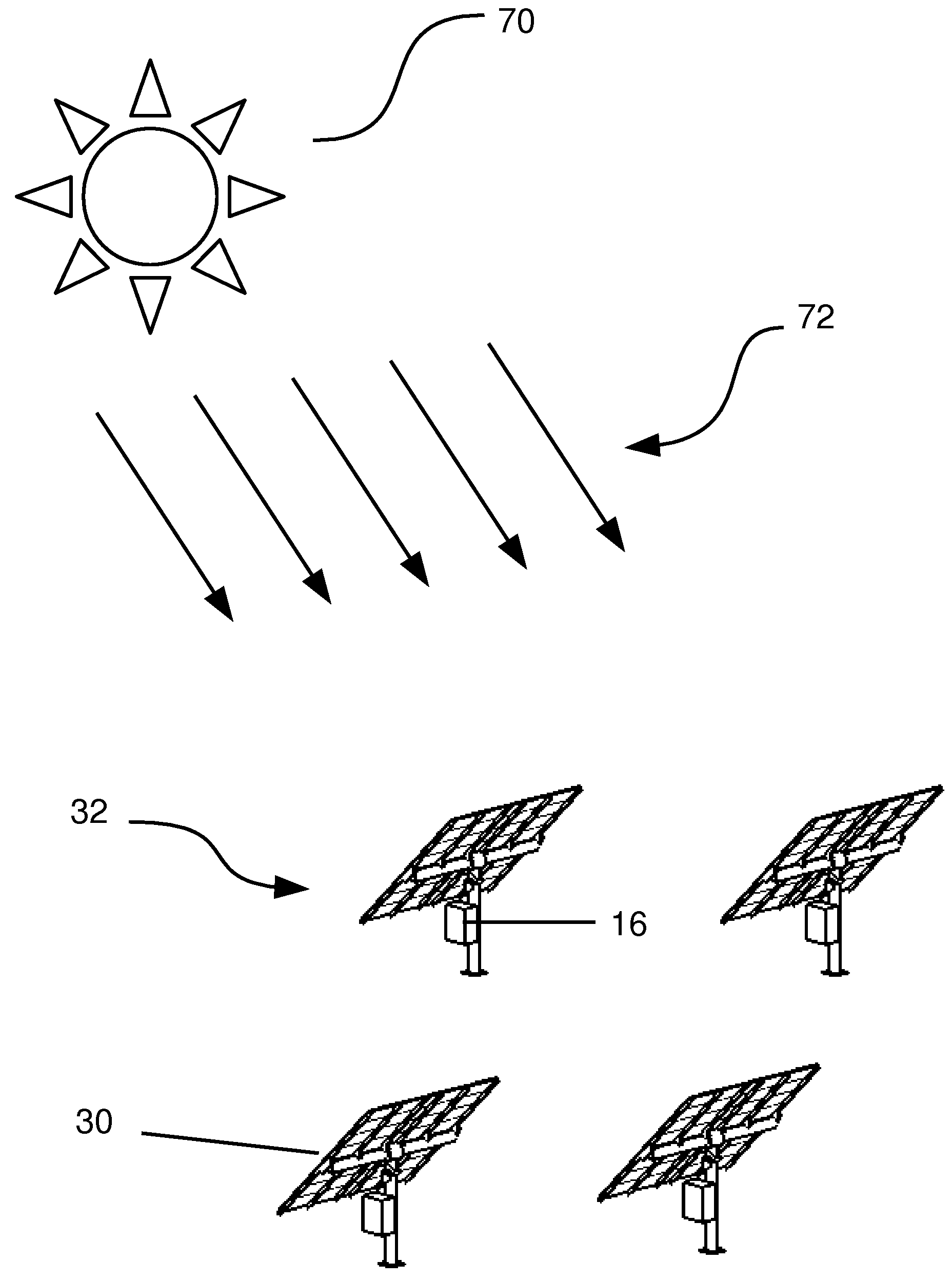
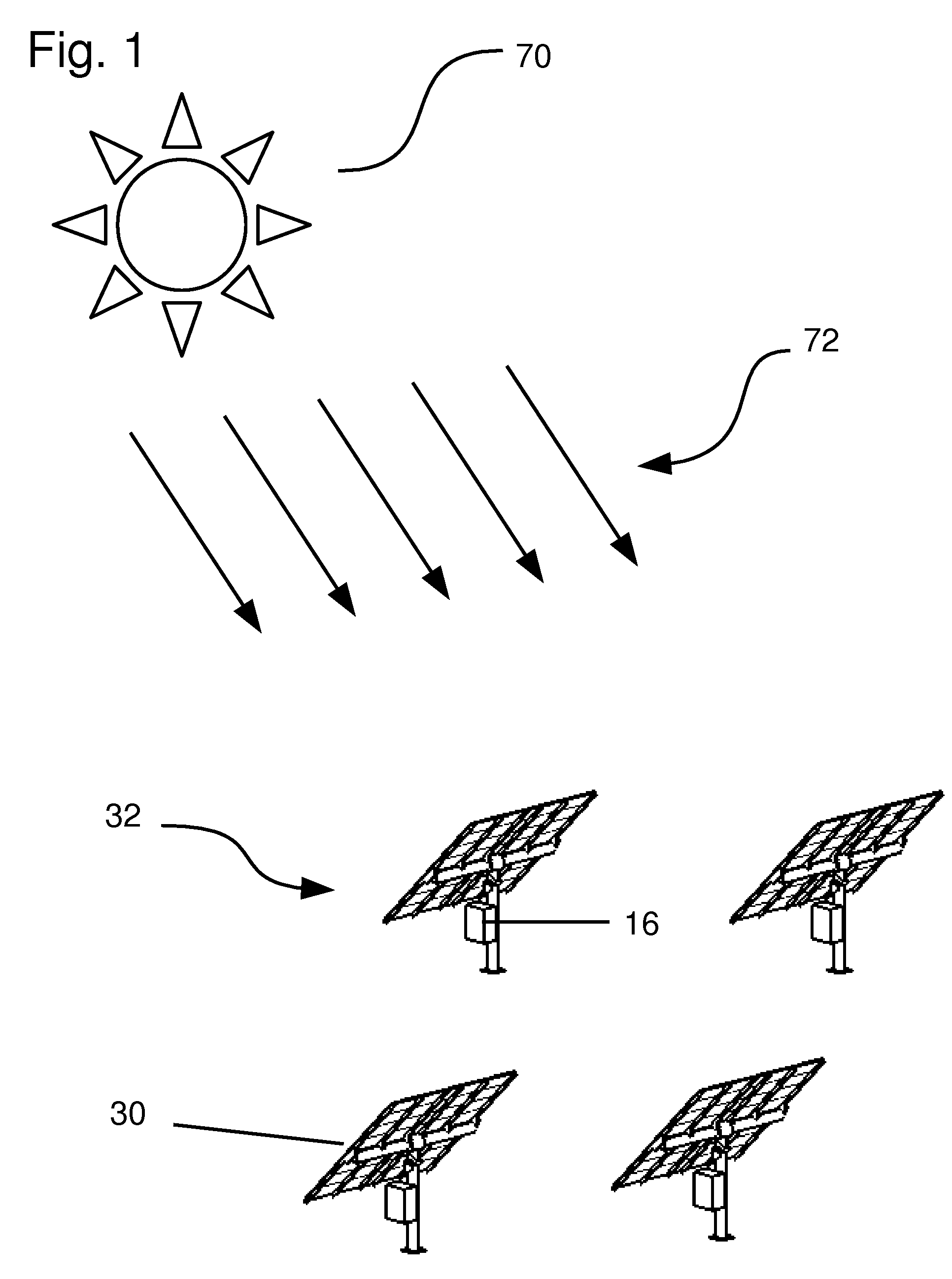
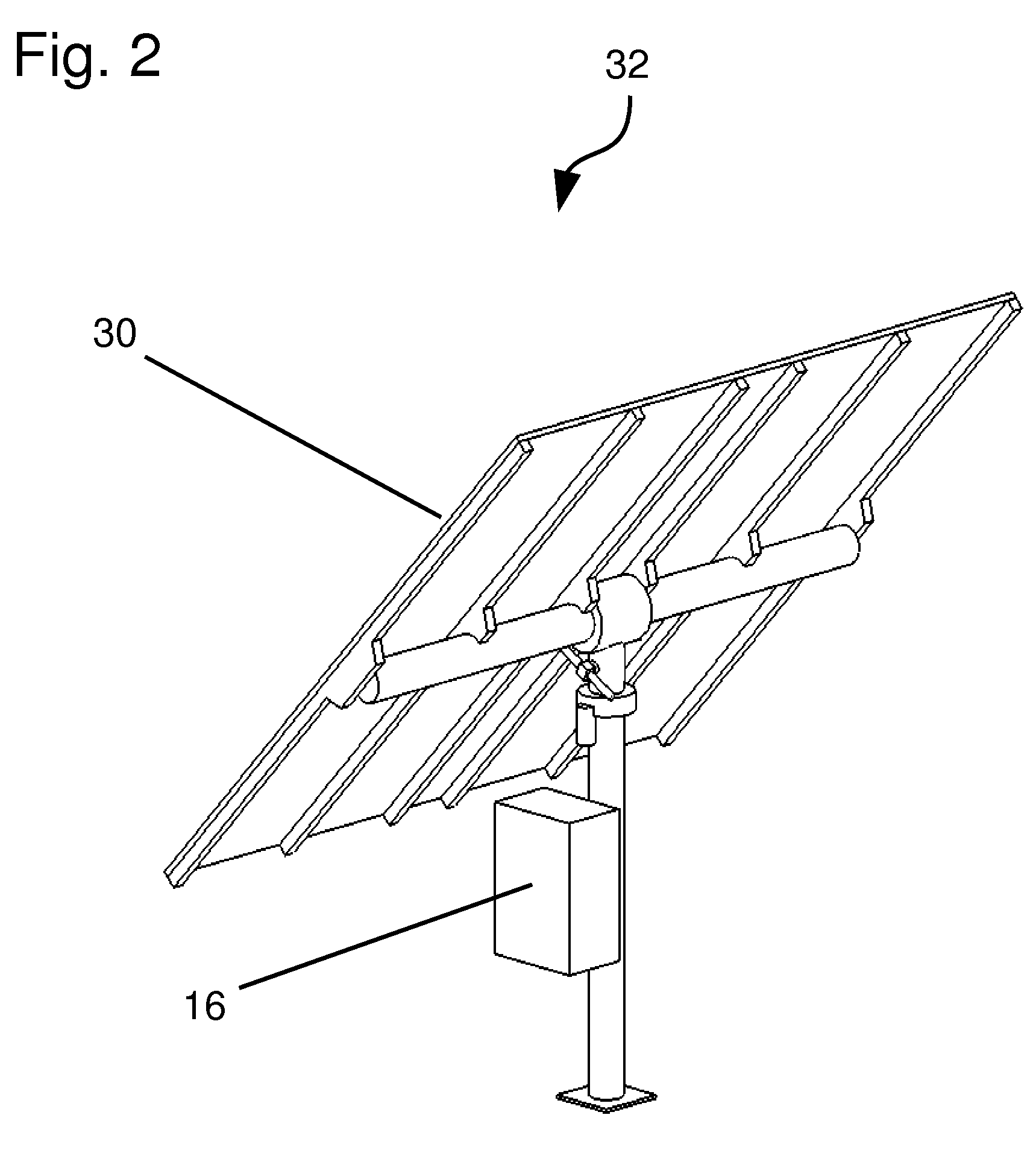
[0032]Referring to FIG. 2, solar tracking device 32 is shown, on which is mounted a tracking controller 16. Tracking controller 16 is responsible for computing both the position of sun 70 and the desired orientation of tracking payload 30 based on variables such as date, time, latitude, and longitude. Based on the results of these calculations, tracking controller 16 can control actuators of tracking device 32 (possibly using sensors of tracking device 32 for this task). In this first embodiment, tracking payload 30 is shown as an array of solar panels.

[0033]Referring to FIG. 3, the data communication paths available in the first embodiment are shown. A host computer 10 communicates via communication channel 12 to host gateway 58. Host gateway 58 in turn communicates with network manager 14. Finally, network manager 14 communicates with tracking controller 16 via a wireless mesh communications network 18. In this first embodiment, base station 56 houses both host gateway 58 and netw...

second embodiment

[0040]Referring to FIG. 8, a representative view of the wireless mesh communications network of this invention is shown. In this embodiment, one of tracking controller 16 provides network manager 14 and host gateway 58.

[0041]Referring to FIG. 9, components of the second embodiment are schematically illustrated. Identical to FIG. 5, communication channel 12 represents the path from host computer 10 to host gateway 58. Network manager 14 and host gateway 58 have identical functions here as in FIG. 5. However, in this second embodiment, base station 56 is not necessary, as tracking device 32′ provides network manager 14 and host gateway 58.

first embodiment (figs.1 , 2 , 3 , 4 , 5 , 6 , 7)

[0042]Operation—First Embodiment (FIGS. 1, 2, 3, 4, 5, 6, 7)

[0043]The apparatus for wireless mesh networking of solar tracking devices 32 of this invention is used in this embodiment to improve aspects of a site that contains a plurality of solar tracking devices 32. Tracking device 32 in this embodiment of the invention comprises senors, actuators, mechanisms, and controls suitable for orienting tracking payload 30 in two axes with respect to sun 70. In this embodiment, tracking payload 30 comprises flat plate solar panels that point directly at sun 70 when this is possible given the mechanism of tracking device 32. This is a common configuration of solar tracking device 32. However, there are many other configurations of tracking device 32 that can be used in other embodiments of this invention. For instance, single axis tracking devices 32 are common that orient tracking payload 30 (again flat plat solar panels) in one axis with respect to sun 70. This type of tracking device 32 ...


PUM


Abstract

An apparatus for networking solar tracking devices 32. The system includes one or more solar tracking devices 32, each comprising tracking controller 16. Tracking controllers 16 form wireless mesh communications network 18 managed by network manager 14. Tracking controller 16 receives operating data from and sends monitoring data to host computer 10. This operation and monitoring data travels across wireless communications network 18. Host computer 10 connects to wireless mesh communications network 18 either directly or via any communication channel 12 connected to any node on wireless mesh communications network 18.

Description

CROSS-REFERENCE TO RELATED APPLICATIONS[0001]Not applicableSTATEMENT REGARDING FEDERALLY SPONSORED RESEARCH OR DEVELOPMENT[0002]Not applicableBACKGROUND OF THE INVENTION[0003]1. Field of the Invention[0004]The present invention relates in general to the field of solar tracking, more particularly to the operation and monitoring of the control systems that orient objects (e.g. solar cells and solar concentrators) with respect to the sun.[0005]2. Prior Art[0006]Companies and municipalities have for many years been burdened with the expensive and cumbersome task of operating and monitoring control systems for solar tracking devices. Solar tracking devices are used to orient solar cells, solar concentrators, or other devices such as testing apparatuses with respect to the sun. The control systems for these solar tracking devices comprise a significant number of sensors, actuators, and algorithms, along with associated wiring, enclosure(s), and power transforming devices. In order to effe...

Claims


Application Information

Patent Timeline
Patent Type & Authority Applications(United States)
IPC IPC(8): F24J2/38F24S50/20
CPCF24J2/38F24J2/40Y02E10/47H04W84/18F24J2/542H02S20/32F24S50/20F24S30/452F24S50/00Y02E10/50
Inventor KRAFT, STEVEN MICHAELJONES, JASON CHARLES
Owner SUNPOWER CORPORATION
Why Eureka
Try Eureka