Renewable energy management and storage system

a technology of renewable energy and management system, applied in the direction of dc source parallel operation, single ac network with different frequencies, energy industry, etc., can solve the problems of affecting the widespread adoption of these energy sources as stand-alone implementations, affecting the environment, and affecting the efficiency of electrical energy storage, so as to achieve the effect of convenient connection

Inactive Publication Date: 2009-07-30
RENEWABLE ENERGY HLDG
View PDF3 Cites 68 Cited by
  • Summary
  • Abstract
  • Description
  • Claims
  • Application Information

AI Technical Summary

Benefits of technology

[0018]Major components of the present invention are housed in a unitary enclosure. Components of the energy storage subsystem, such as the battery / ultracapacitor bank, and hydrogen storage tank, can be housed in one or more separate enclosures that easily connect to the rest of the system.

Problems solved by technology

However, several existing technical problems hinder the widespread adoption of these energy sources as stand-alone implementations, as well as their integration into the existing power infrastructure.
Because of the nature of these renewable energy sources, the power supplied tends to be intermittent and unreliable (“intermittency problem”).
The current electrical energy storage means of overcoming this intermittency problem are bulky, inefficient, expensive, and harmful to the environment.
However, for household or business consumption, the power supply would often need to be alternating current (AC).
A conventional regenerative fuel cell system usually includes multiple inverters, power supplies, and regulators for each of the different components, e.g., the electrolyzer and fuel cell require separate power supplies and inverters, which usually leads to an unnecessarily complex system, and drives up the capital requirement, and installation and maintenance cost of the system.
However, integration of the renewable energy system with the existing public utility grid is still cumbersome and expensive, which also hinders the adoption of renewable energy.

Method used


Image

  • Renewable energy management and storage system
  • Renewable energy management and storage system
  • Renewable energy management and storage system

Examples


Embodiment Construction

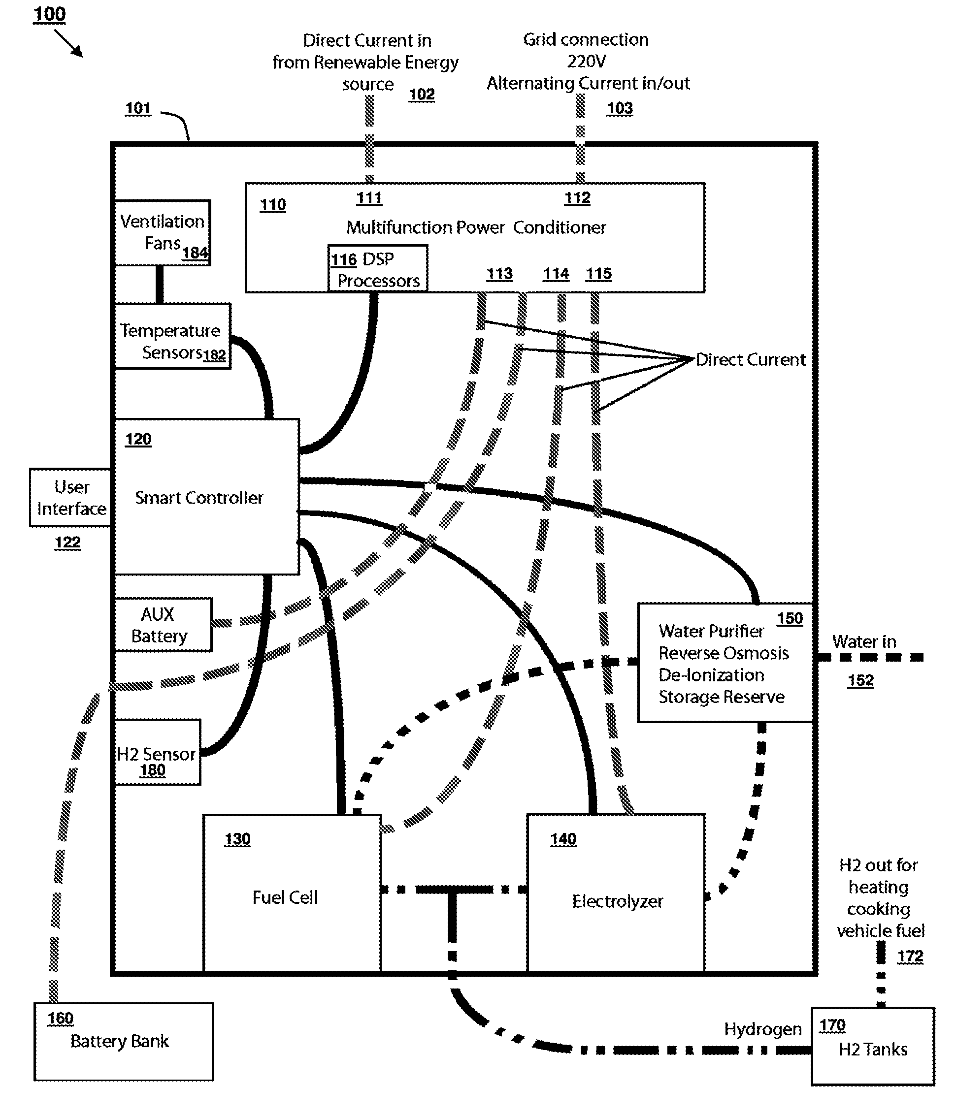
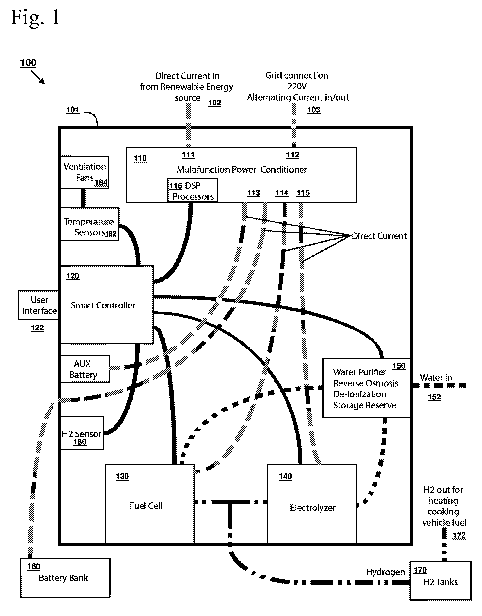
[0024]The present invention teaches an integrated system of renewable energy management and storage. The system supplies all energy needs without a carbon footprint. No fossil or limited fuel is used or required in the operation of the system. The system can be used in connection with a public utility grid or as a stand-alone system that does not connect to a utility grid. The use of the system of the present invention can significantly reduce or eliminate future energy costs and allow for the accurate estimate of future energy costs.

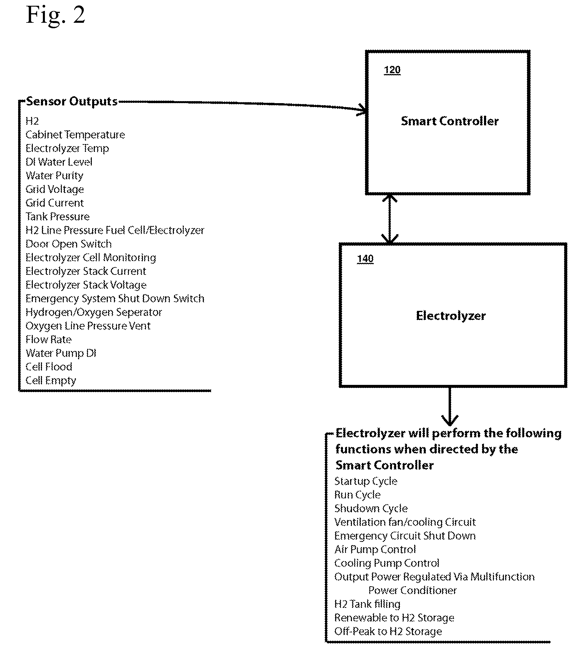
[0025]The present invention comprises of a Multifunctional Power Conditioner, a Smart Controller, and an energy storage subsystem. The system connects to any direct current (DC) producing renewable energy sources, such as solar, wind, hydroelectric, biomass, and geothermal generators, and supplies alternating current for home or business consumption.

[0026]The system provides a continuous power reserve during power generation interruption. If the system ...


PUM


Abstract

An integrated system of renewable energy management and storage that receives direct current generated from renewable sources and intelligently routes the electrical power between a direct current circuit and an alternating current circuit, and at the same time determines the optimal routing for electrical storage based on usage and demand. Electrical power from the direct current circuit can be converted to alternating current electrical power and supplied to the alternating current circuit, or vice versa. Electrical power from either the direct current circuit or the alternating current can be stored in the energy storage subsystem. Electric energy can be further converted to and stored as gaseous hydrogen and can supply for other applications that consume gaseous hydrogen. The system can work with a connection to a utility grid or as a stand-alone system.

Description

REFERENCE TO RELATED APPLICATIONS[0001]This application claims one or more inventions which were disclosed in Provisional Application No. 61 / 023256, filed Jan. 24, 2008, and entitled “RENEWABLE ENERGY MANAGEMENT AND STORAGE SYSTEM”. The benefit under 35 USC §119(e) of the United States provisional application is hereby claimed, and the aforementioned application is hereby incorporated herein by reference.BACKGROUND OF THE INVENTION[0002]1. Field of the Invention[0003]This invention relates generally to electric energy generation and storage, and the management thereof. Specifically, the present invention relates to an integrated system that converts, stores, and manages energy harvested from renewable sources to provide uninterrupted electrical output, and gaseous hydrogen output.[0004]2. Description of Related Art[0005]Renewable energy sources are attracting more attention as the global climate change resulting from human activity becomes apparent. Renewable energy sources such as ...

Claims


Application Information

Patent Timeline
Patent Type & Authority Applications(United States)
IPC IPC(8): H02J5/00
CPCH02J3/382H02J7/34H02J3/387H02J3/383Y02E10/763H02J3/386Y02E10/563Y02E10/58H02J3/385H02J2300/30H02J2300/28H02J2300/20H02J2300/26H02J2300/24H02J3/381Y02E10/56Y02E10/76Y02P80/20
Inventor STRIZKI, MICHAEL
Owner RENEWABLE ENERGY HLDG
Why Eureka
Try Eureka