Eureka AIR delivers breakthrough ideas for toughest innovation challenges, trusted by R&D personnel around the world.

Piezoelectric vibrating reed, piezoelectric vibrator, oscillator, electronic device, wave clock, and manufacturing method of piezoelectric vibrating reed

Active Publication Date: 2009-07-30
SII CRYSTAL TECH
View PDF7 Cites 2 Cited by
  • Summary
  • Abstract
  • Description
  • Claims
  • Application Information

AI Technical Summary

Benefits of technology

[0022]In particular, in the electrode forming step, the base metal layer and the finishing metal layer are not laminated across the entire outer surfaces of the piezoelectric plate, and instead, the electrode film is formed in such a manner that the finishing metal layer is removed either partially or entirely at least in the region from the base end portions to the tip end portions of the vibrating arms. The electrode film formed on the vibrating arms is therefore a single-layer film formed of the base metal layer alone either partially or entirely. It thus becomes possible to lessen the film thickness of the electrode film coated on the vibrating arms.
[0047]According to the oscillator, the electronic device, and the wave clock of the invention, because each includes the piezoelectric vibrator as above, the size can be reduced and the quality can be enhanced as with the piezoelectric vibrator.

Problems solved by technology

A size reduction of the piezoelectric vibrating reed therefore gives rise to an inconvenience that the R1 value (serial resonance resistance value) becomes higher.
In particular, because the R1 value is proportional to the effective resistance value Re, when the R1 value becomes higher, there arises a problem that it becomes difficult to operate the piezoelectric vibrating reed on low power.
However, there is a processing limitation in forming a groove portion in the vibrating arm that has been made smaller.
More specifically, because the vibrating arms themselves become smaller due to a size reduction, it is extremely difficult to form the groove portions in the vibrating arms that have been made smaller.
Hence, there is a case that the piezoelectric vibrating reed fails to ensure a desired R1 value.

Method used


Image

  • Piezoelectric vibrating reed, piezoelectric vibrator, oscillator, electronic device, wave clock, and manufacturing method of piezoelectric vibrating reed
  • Piezoelectric vibrating reed, piezoelectric vibrator, oscillator, electronic device, wave clock, and manufacturing method of piezoelectric vibrating reed
  • Piezoelectric vibrating reed, piezoelectric vibrator, oscillator, electronic device, wave clock, and manufacturing method of piezoelectric vibrating reed

Examples


Embodiment Construction

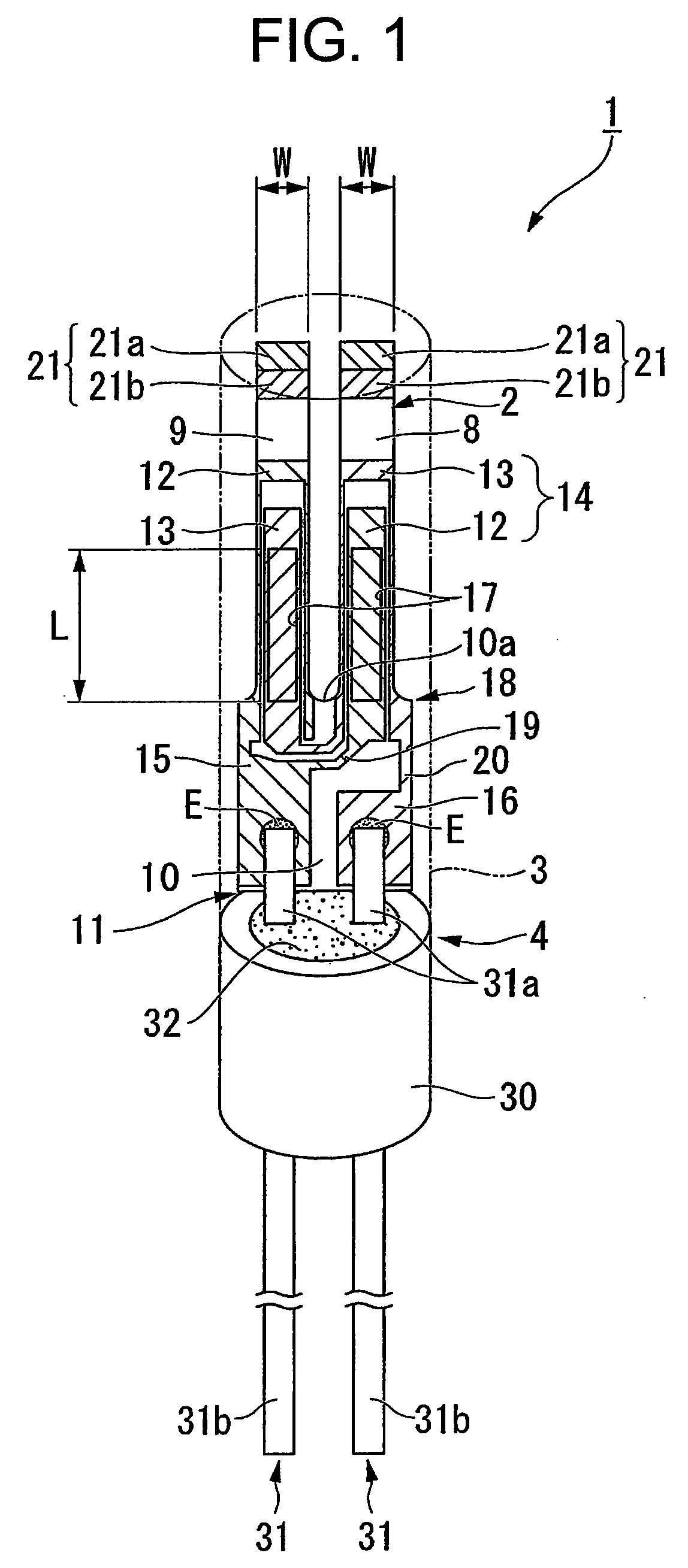
[0074]Hereinafter, one embodiment of the invention will be described with reference to FIG. 1 through FIG. 21. This embodiment will describe a piezoelectric vibrator 1, which is a cylinder package type piezoelectric vibrator, by way of example.

[0075]As are shown in FIG. 1 through FIG. 6, the piezoelectric vibrator 1 of this embodiment includes a piezoelectric vibrating reed 2, a case 3 that accommodates the piezoelectric vibrating reed 2 inside, and a plug 4 that is an airtight terminal to hermetically seal the piezoelectric vibrating reed 2 inside the case 3.

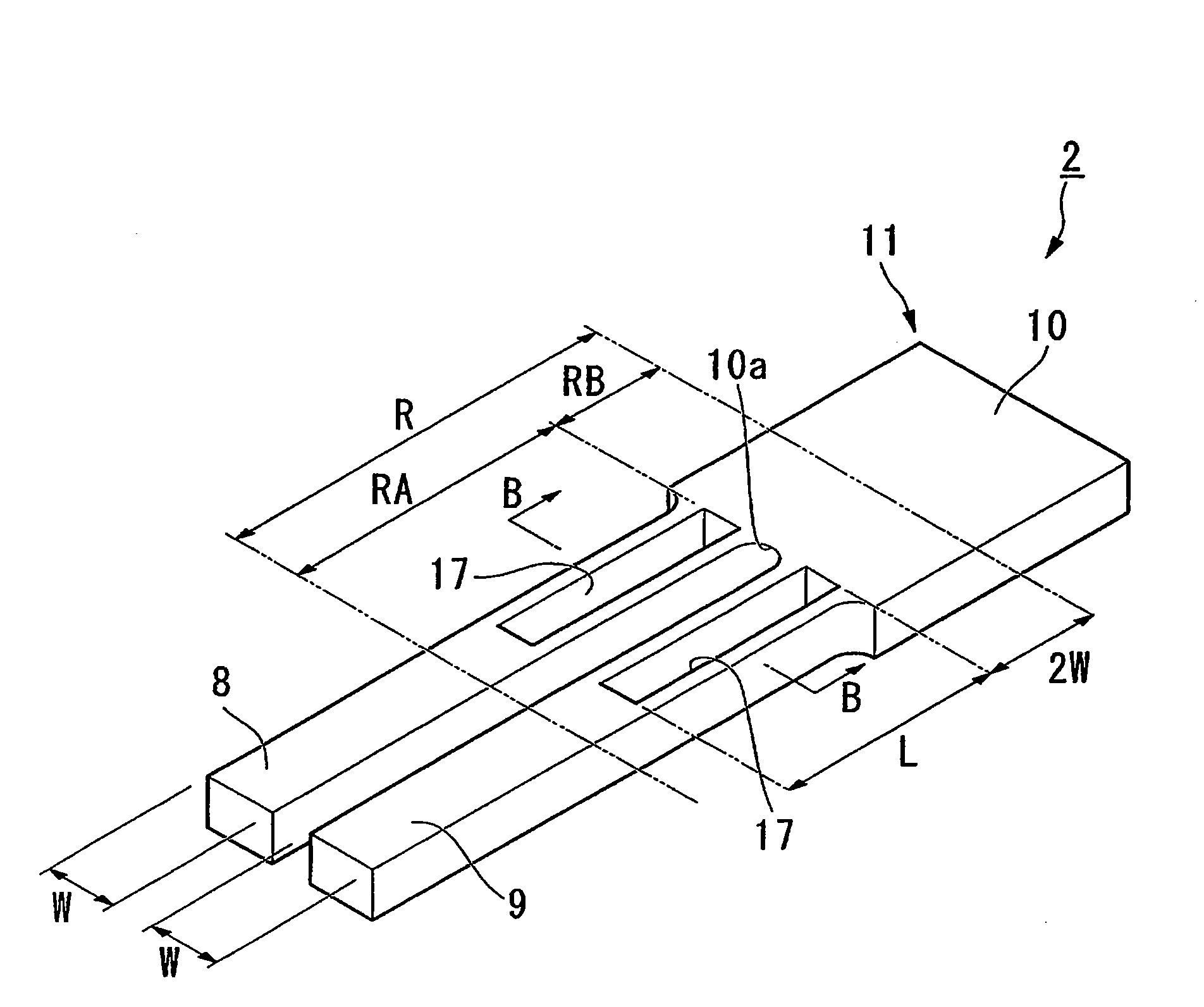
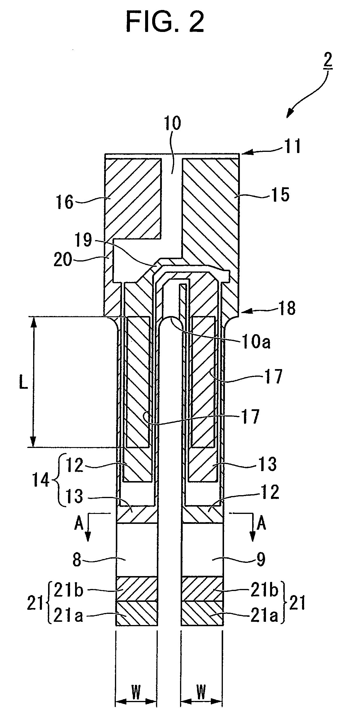
[0076]As are shown in FIG. 2 through FIG. 6, the piezoelectric vibrating reed 2 is a tuning-fork vibrating reed made of a piezoelectric material, such as quartz, lithium tantalate, and lithium niobate, and vibrates when a predetermined voltage is applied thereon. In FIG. 5, an electrode film 18 and a weight metal film 21 described below are omitted.

[0077]As are shown in FIG. 2 and FIG. 3, the piezoelectric vibrating reed 2 incl...


PUM

PropertyMeasurementUnit
Lengthaaaaaaaaaa

Abstract

A piezoelectric vibrating reed includes a piezoelectric plate having a pair of vibrating arms provided parallel to each other, a base portion to integrally fix the pair of vibrating arms at a base end side thereof, and groove portions formed on both principal surfaces of the pair of vibrating arms in a constant length from base end portions toward tip end portions of the vibrating arms, and an electrode film formed of a base metal layer and a finishing metal layer laminated on outer surfaces of the piezoelectric plate and configured to vibrate the pair of vibrating arms when a predetermined voltage is applied thereon. The finishing metal layer of the electrode film is removed either partially or entirely at least in regions from the base end portions to the tip end portions of the vibrating arms.

Description

RELATED APPLICATION[0001]This application claims priority under 35 U.S.C. §119 to Japanese Patent Application No. JP2008-018555 filed on Jan. 30, 2008, the entire content of which is hereby incorporated by reference.BACKGROUND OF THE INVENTION[0002]1. Field of the Invention[0003]The present invention relates to a tuning-fork piezoelectric vibrating reed, a piezoelectric vibrator having the piezoelectric vibrating reed, and an oscillator, an electronic device, and a wave clock each having the piezoelectric vibrator, as well as a manufacturing method of the piezoelectric vibrating reed.[0004]2. Background Art[0005]Recently, a piezoelectric vibrator utilizing quartz or the like is used in a cell-phone and a personal digital assistance as the time source, the timing source of a control signal, a reference signal source, and so forth. The piezoelectric vibrator of this type is proposed in a variety of forms, and a type having a tuning-fork piezoelectric vibrating reed is one example.[000...

Claims


Application Information

Patent Timeline
IPC IPC(8): H01L41/047H01L41/04H01L41/24H01L41/09H01L41/18H01L41/22H01L41/29H01L41/332H01L41/338H03B5/32H03H3/02H03H9/19H03H9/215
CPCH03H3/02Y10T29/42H03H2003/026H03H9/21
Inventor KOBAYASHI, TAKASHI
Owner SII CRYSTAL TECH
Why Eureka
Eureka Blog
Learn More