Supercharge Your Innovation With Domain-Expert AI Agents!

High efficiency charging circuit and power supply system having such high efficiency charging circuit

Active Publication Date: 2009-07-30
DELTA ELECTRONICS INC
View PDF1 Cites 22 Cited by
  • Summary
  • Abstract
  • Description
  • Claims
  • Application Information

AI Technical Summary

Benefits of technology

[0008]It is an object of the present invention to provide charging circuit, having a high operating efficiency independent of the charge capacity of the battery so as to obviate the drawbacks encountered from the prior art.

Problems solved by technology

If the power supplied from the battery is insufficient, the user needs to charge the built-in battery.
On the whole, the operating efficiency of the charging circuit 1 is unsatisfactory.

Method used


Image

  • High efficiency charging circuit and power supply system having such high efficiency charging circuit
  • High efficiency charging circuit and power supply system having such high efficiency charging circuit
  • High efficiency charging circuit and power supply system having such high efficiency charging circuit

Examples


Embodiment Construction

[0017]The present invention will now be described more specifically with reference to the following embodiments. It is to be noted that the following descriptions of preferred embodiments of this invention are presented herein for purpose of illustration and description only. It is not intended to be exhaustive or to be limited to the precise form disclosed.

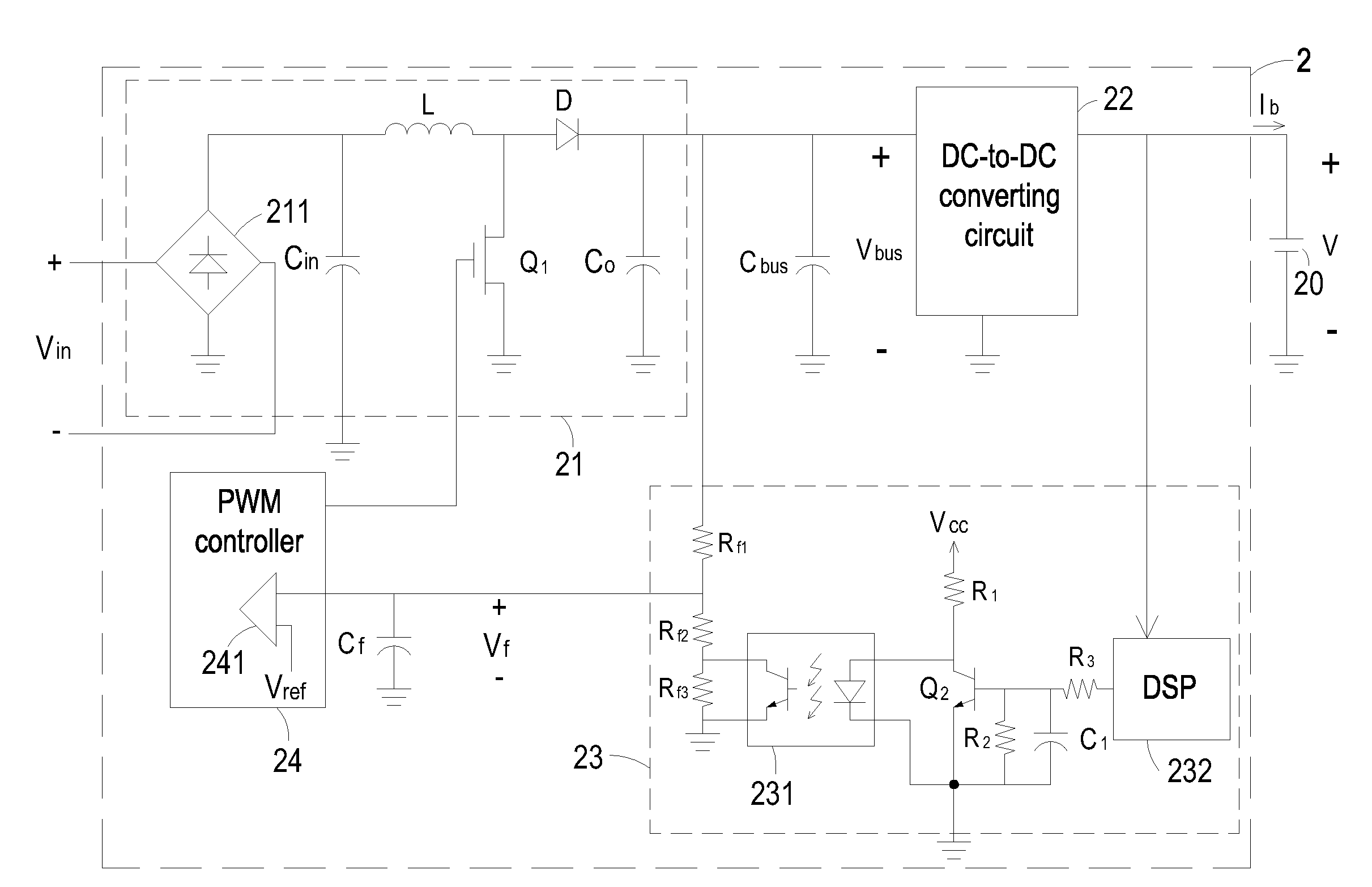
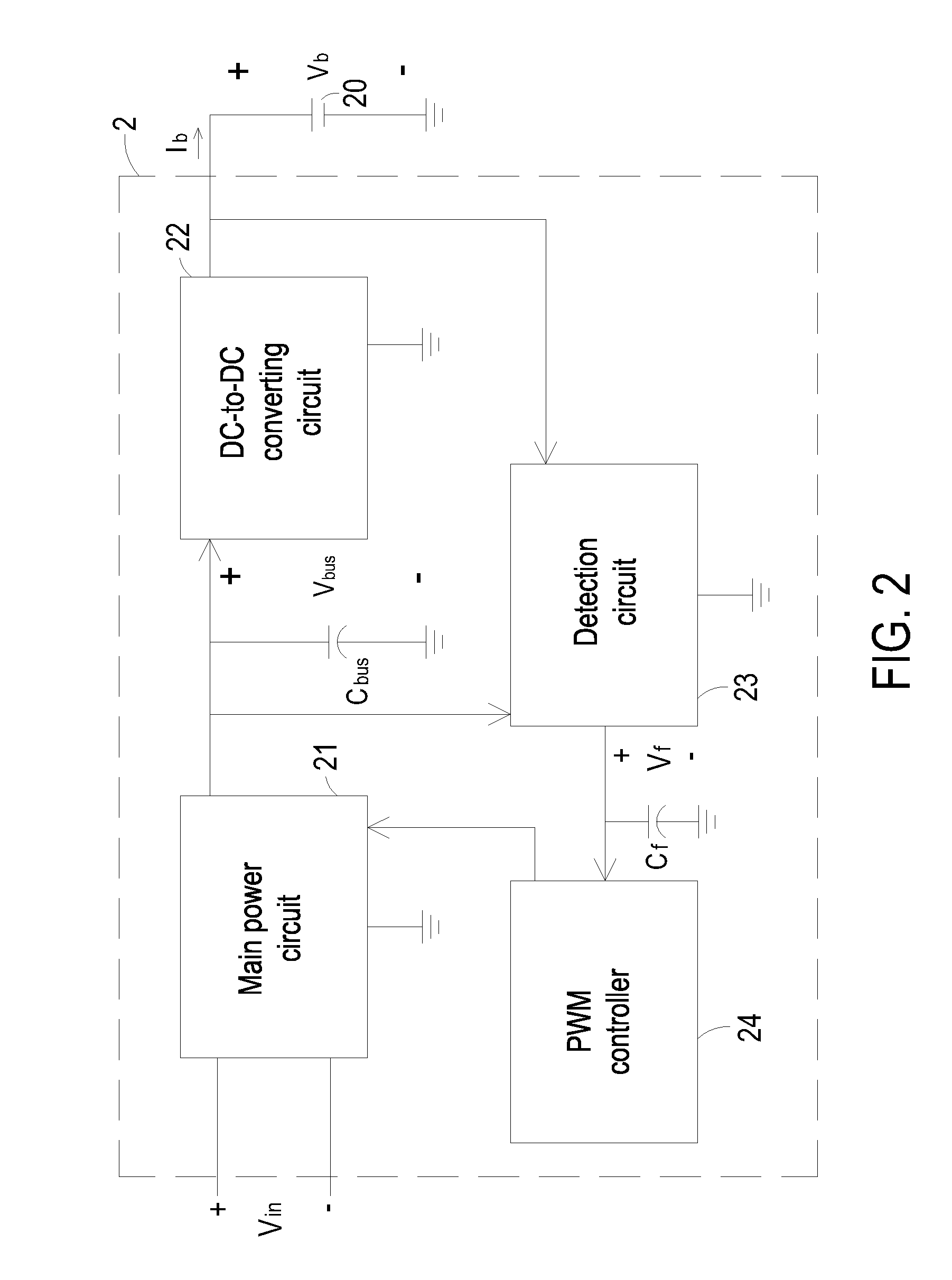
[0018]Referring to FIG. 2, a schematic circuit block diagram of a high efficiency charging circuit according to a preferred embodiment of the present invention is illustrated. This high efficiency charging circuit 2 is adapted to charge an energy storage element 20. An example of the energy storage element 20 includes but is not limited to a battery. The high efficiency charging circuit 2 of FIG. 2 principally includes a main power circuit 21, a DC-to-DC converting circuit 22, a detection circuit 23 and a pulse width modulation (PWM) controller 24. The main power circuit 21 is electrically connected to a power source so as to rec...


PUM


Abstract

A charging circuit includes a main power circuit, a DC-to-DC converting circuit, a detection circuit and a controller. The main power circuit is electrically connected to a power source for converting an input voltage from the power source into a first voltage. The DC-to-DC converting circuit is electrically connected to the main power circuit for converting the first voltage into a second voltage to charge the energy storage element. The detection circuit is electrically connected to the main power circuit and the DC-to-DC converting circuit for detecting a terminal voltage of the energy storage element and the first voltage from the main power circuit, thereby generating a feedback signal. The controller is electrically connected to the detection circuit and the main power circuit for controlling operations of the first switching element in response to the feedback signal, so that the first voltage is adjustable according to the second voltage.

Description

FIELD OF THE INVENTION[0001]The present invention relates to a charging circuit, and more particularly to a high efficiency charging circuit. The present invention also relates to a power supply system having such a high efficiency charging circuit.BACKGROUND OF THE INVENTION[0002]Recently, the general trends in designing portable electronic devices are toward small size, light weightiness and easy portability. The portable electronic devices such as mobile phones, personal digital assistants (PDAs), digital still cameras, digital video cameras, notebook computers and the like have built-in batteries. If no external power supply apparatus is provided to power the portable electronic device, the built-in battery is usually used as the main power source. If the power supplied from the battery is insufficient, the user needs to charge the built-in battery.[0003]FIG. 1 is a schematic circuit block diagram of a conventional charging circuit. The charging circuit 1 of FIG. 1 principally i...

Claims


Application Information

Patent Timeline
IPC IPC(8): H02J7/04
CPCH02J7/022H02M1/4225Y02B70/126Y02B40/90H02M2001/007H02J7/02H02J2207/20Y02B40/00Y02B70/10H02M1/007
Inventor LAI, YUAN-FANGHUANG, MIN-CHOUWANG, CHIU-FENG
Owner DELTA ELECTRONICS INC
Features
  • R&D
  • Intellectual Property
  • Life Sciences
  • Materials
  • Tech Scout
  • Unparalleled Data Quality
  • Higher Quality Content
  • 60% Fewer Hallucinations
Learn More