Magnetic sensor and rotation-angle-detecting apparatus

a technology of rotation angle and detecting apparatus, which is applied in the field of magnetic sensors, can solve the problems of increasing angle error, affecting the accuracy of rotation angle sensors, and unable to provide output signals with small angle error and distortion, so as to reduce angle error

Active Publication Date: 2009-07-30
HITACHI METALS LTD
View PDF5 Cites 53 Cited by
  • Summary
  • Abstract
  • Description
  • Claims
  • Application Information

AI Technical Summary

Benefits of technology

[0006]Accordingly, an object of the present invention is to provide a magnetic sensor with reduced angle error that is gener

Problems solved by technology

However, this rotation angle sensor fails to absorb unevenness in a wafer plane.
Therefore, a bridge circuit with such device arrangement provides only an output having the same phase, failing to obtain a full-bridge output.
Also, a device arrangement having an angle of 90° between devices cannot provide output signals with small angle error and distortion.
However, th

Method used


Image

  • Magnetic sensor and rotation-angle-detecting apparatus
  • Magnetic sensor and rotation-angle-detecting apparatus
  • Magnetic sensor and rotation-angle-detecting apparatus

Examples


embodiment 1

[0074]Angle Error of Magnetic Sensor Having Parallel Device Arrangement

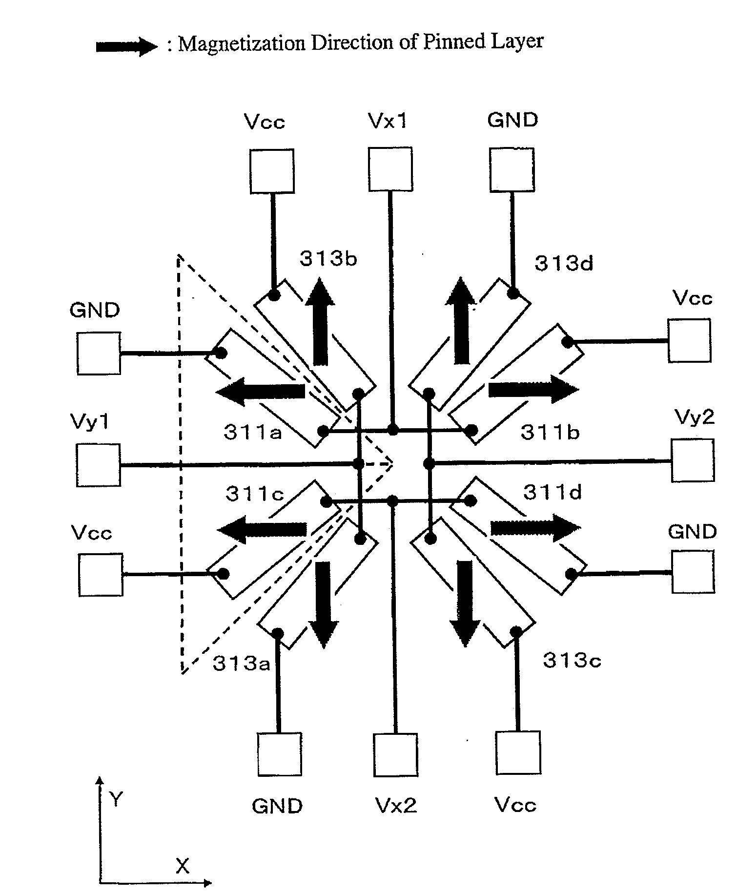
[0075]FIG. 11 shows a magnetic sensor comprising bridges X and Y constituted by SVGMR devices. In the bridge X, four rectangular SVGMR devices 201a-201d are formed on a substrate by patterning, the devices 201b and 201c being connected to a power supply terminal Vcc, the devices 201a and 201d being connected to a ground terminal GND, the devices 201a and 201b being connected to one output terminal Vx1, and the devices 201c and 201d being connected to the other output terminal Vx2. The longitudinal directions of the devices 201a-201d are inclined by angles θdip-R1-θdip-R4 relative to an axis 202 parallel to the magnetization directions of pinned layers shown by thick arrows. In the bridge Y, four rectangular SVGMR devices 203a-203d are formed on a substrate by patterning, each perpendicular to the corresponding devices 201a-201d in the bridge X. Although the magnetization direction of a pinned layer of each device...

embodiment 2

[0084]Angle Error of Magnetic Sensor with Non-Parallel Device Arrangement

[0085]To suppress the power consumption of a magnetic sensor by increasing the resistance of SVGMR devices, some devices have longitudinal sizes of about several tens of micrometers to one hundred micrometers. Such long devices increase the shape-induced anisotropy of a free layer in an SVGMR film. In such circumstances, the AMR effect differently affects the angle error of the magnetic sensor. Accordingly, θdip-R1 was changed as shown in Table 3 in a magnetic sensor having the device arrangement shown in FIG. 11 to determine Δθerr by simulation in both cases where the AMR effect was included and neglected. The results are shown in FIG. 21. In Table 3, the anticlockwise angle is expressed by “+.” In the formula (8), it was assumed from the thickness ratio of a free layer to the SVGMR film and the specific resistance of a NiFe film that the resistance contributing to AMR was 7500Ω, and that the AMR ratio was 0.3...

embodiment 3

[0093]Investigation of Influence of Hint Variation on Angle Error

[0094]The most variable magnetic property in the SVGMR film is a magnetic field Hint acting between a pinned layer and a free layer via an intermediate layer. Hint is easily variable depending on the thickness variation of the intermediate layer, a so-called “orange peel effect” due to the surface roughness of the intermediate layer, temperatures such as an operation temperature and an ambient temperature, etc. To determine the relation between Hint and Δθerr in the optimum device arrangement (Example 2), Δθerr was determined by simulation with the Hint of the device 213a (Hint-R5) changed from −0.8 kA / m to +0.8 kA / m at Hint-R1 of 0 kA / m, 0.08 kA / m, 0.16 kA / m, 0.40 kA / m and 0.80 kA / m, in the magnetic sensor shown in FIG. 12. The results are shown in FIG. 26.

Hint-R1 of device 211a=Hint-R4 of device 211d,

Hint-R2 of device 211b=Hint-R3 of device 211c,

Hint-R1=−Hint-R2,

Hint-R5 of device 213a=Hint-R8 of device 213d,

Hint-R...


PUM


Abstract

A magnetic sensor comprising a bridge circuit in which four magnetoresistive devices are connected, the magnetoresistive device comprising a spin-valve, giant-magnetoresistive film comprising a pinned layer having unidirectional magnetic anisotropy, a free layer whose magnetization direction is rotated in alignment with an external magnetic field direction, and an intermediate layer sandwiched by the pinned layer and the free layer, and at least one of the magnetoresistive devices meeting the condition of 36°≦θ<45°, wherein θ is an acute angle between its longitudinal direction and the magnetization direction of the pinned layer.

Description

FIELD OF THE INVENTION[0001]The present invention relates to a magnetic sensor comprising magnetoresistive devices each formed by a spin-valve, giant-magnetoresistive film, and a rotation-angle-detecting apparatus.BACKGROUND OF THE INVENTION[0002]Magnetic sensors using magnetoresistive devices capable of detecting the change of a rotation angle, etc. without contact are required to have good detection sensitivity to a rotating magnetic field. Used for high-sensitivity magnetoresistive devices is a spin-valve, giant-magnetoresistive (SVGMR) film comprising a pinned layer having magnetization anisotropy (simply called “pinned layer”), a non-magnetic intermediate layer formed on the pinned layer for cutting magnetic coupling, and a free layer formed on the non-magnetic intermediate layer and having a magnetization direction rotatable to an arbitrary direction by an external magnetic field. A Wheatstone bridge comprising devices each having the SVGMR film provides a magnetic sensor whos...

Claims


Application Information

Patent Timeline
IPC IPC(8): G01B7/30
CPCB82Y25/00G01R33/093G01D5/145
Inventor OKADA, YASUYUKIMITSUMATA, CHIHARU
Owner HITACHI METALS LTD
Why Eureka
Try Eureka