Method for Coupling a Direct Current Power Source Across a Nearly Frictionless High-Speed Rotation Boundary

a high-speed rotation boundary, fast technology, applied in the direction of electric variable regulation, process and machine control, instruments, etc., to achieve the effect of more friction

Inactive Publication Date: 2009-07-30
UNITED STATES OF AMERICA
View PDF7 Cites 5 Cited by
  • Summary
  • Abstract
  • Description
  • Claims
  • Application Information

AI Technical Summary

Benefits of technology

[0010]It is a further object of the present invention to provide a method for coupling a DC power source across a nearly frictionless and high speed rotating boundary.
[0011]To attain the objects described, a method is disclosed for coupling DC power across a rotating boundary, in which the boundary may be operating at a high speed of rotation. The method incorporates balanced concentric cylinders separated by a dielectric medium that form capacitor couplings. However, anyone skilled in the art will recognize that the method can also be realized by a dual method wherein a magnetic coupling mechanism is effected by placing coupled coils on topologically opposite sides of a non-magnetic rotating boundary. While this application will focus on capacitive coupling in order to teach the method, the dual magnetically coupled mode is claimed implicitly. The dielectric medium can be a vacuum, a gas, or a non-conducting liquid.
[0012]If the dielectric medium is a vacuum or a gas, then the method would be nearly frictionless and no presently measurable mechanical or electrical friction losses would result. A liquid dielectric, which would introduce more friction, may allow application of the method in cases involving rotary joints that penetrate a sealed environment.
[0013]The disclosed method also permits external control of a DC field current without the need for brushes or wiper contacts. Brushes and wiper contacts introduce friction, which is a potential for intermittent contact. Contact also requires regular maintenance of the equipment impacted. Many rotating field alternators are in use today in power generation systems.

Problems solved by technology

A problem arises in connection with electronic circuits for sensing or control that are placed on a rotating platform.

Method used


Image

  • Method for Coupling a Direct Current Power Source Across a Nearly Frictionless High-Speed Rotation Boundary
  • Method for Coupling a Direct Current Power Source Across a Nearly Frictionless High-Speed Rotation Boundary
  • Method for Coupling a Direct Current Power Source Across a Nearly Frictionless High-Speed Rotation Boundary

Examples


Embodiment Construction

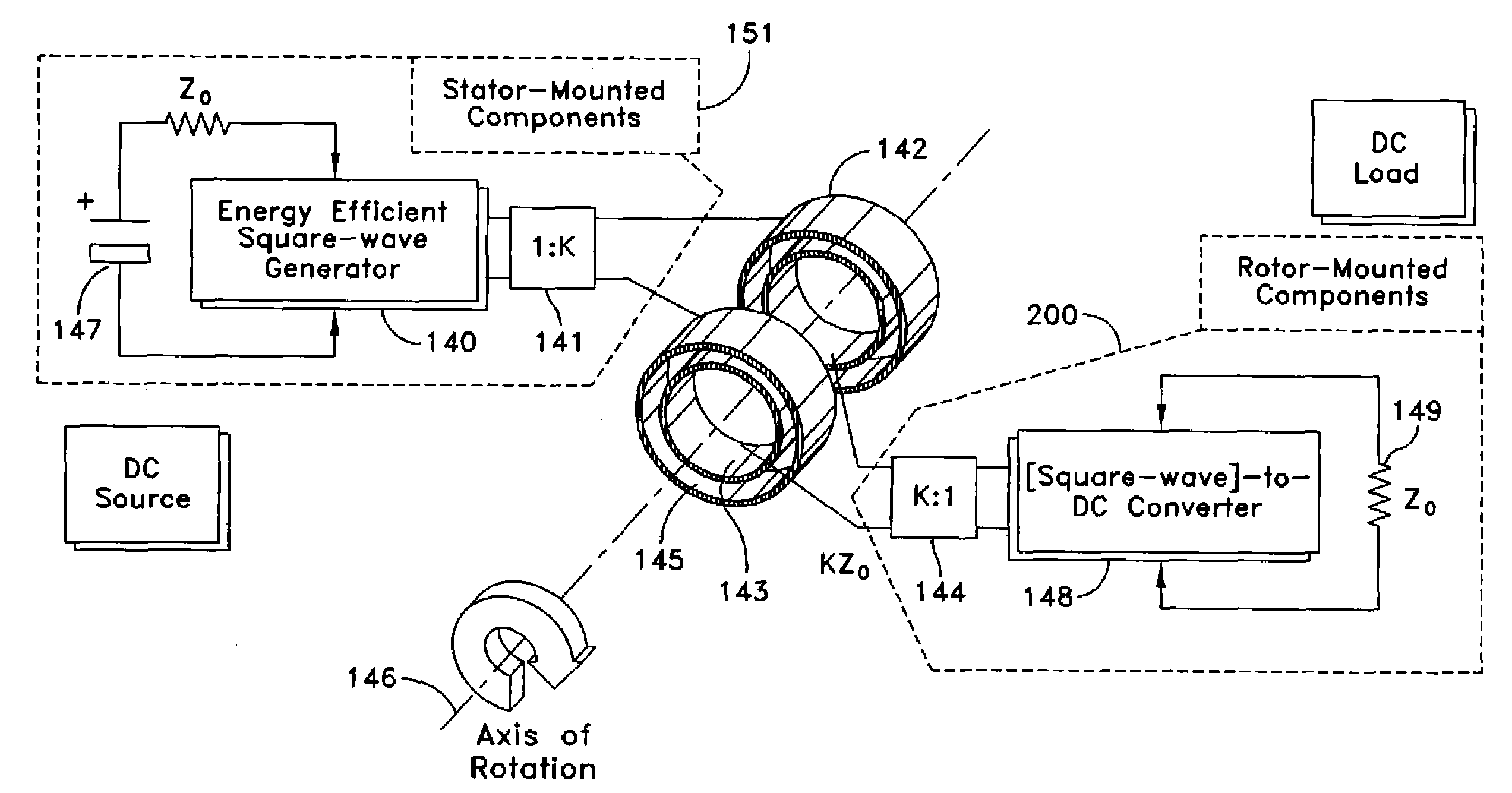
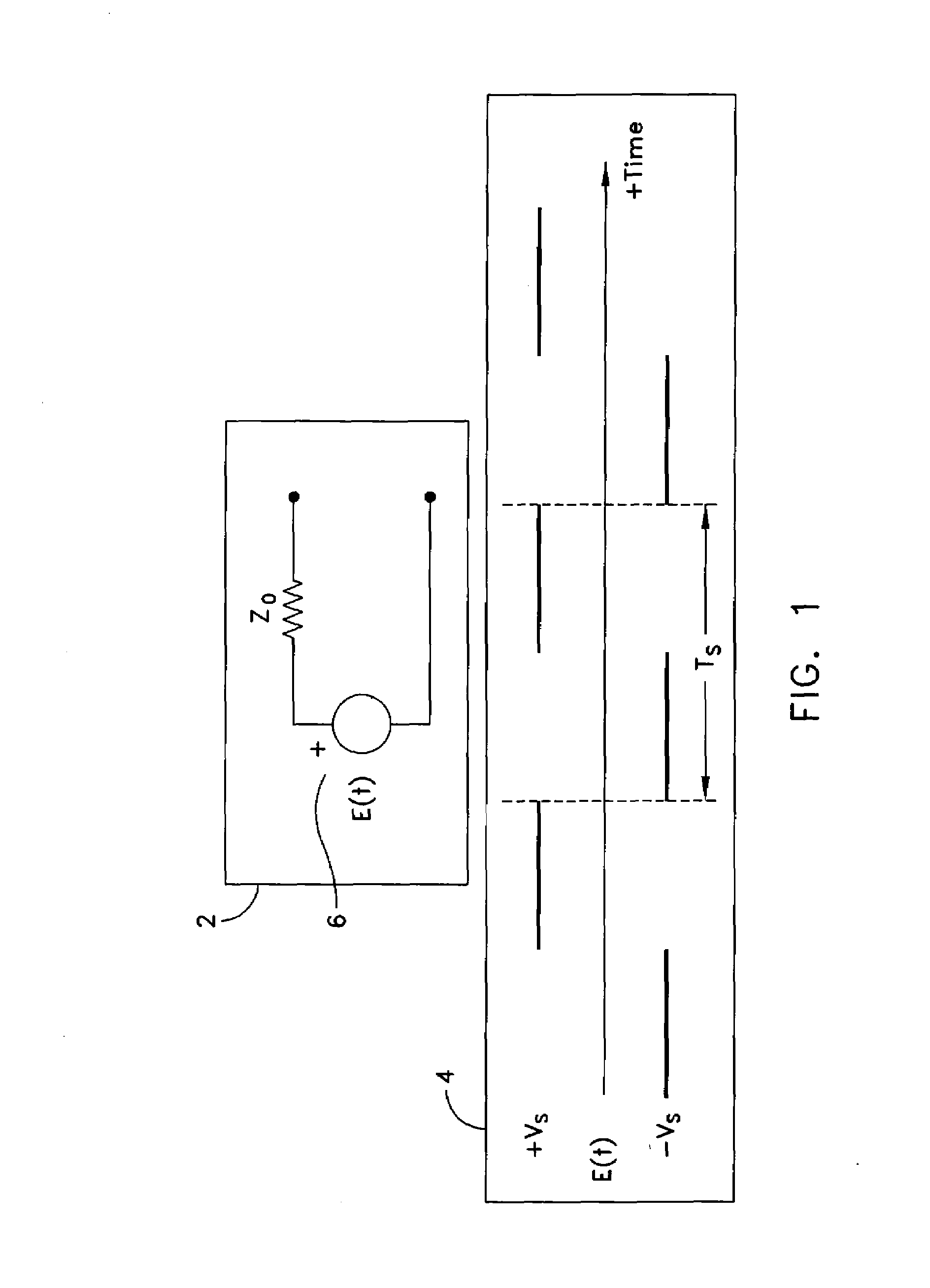
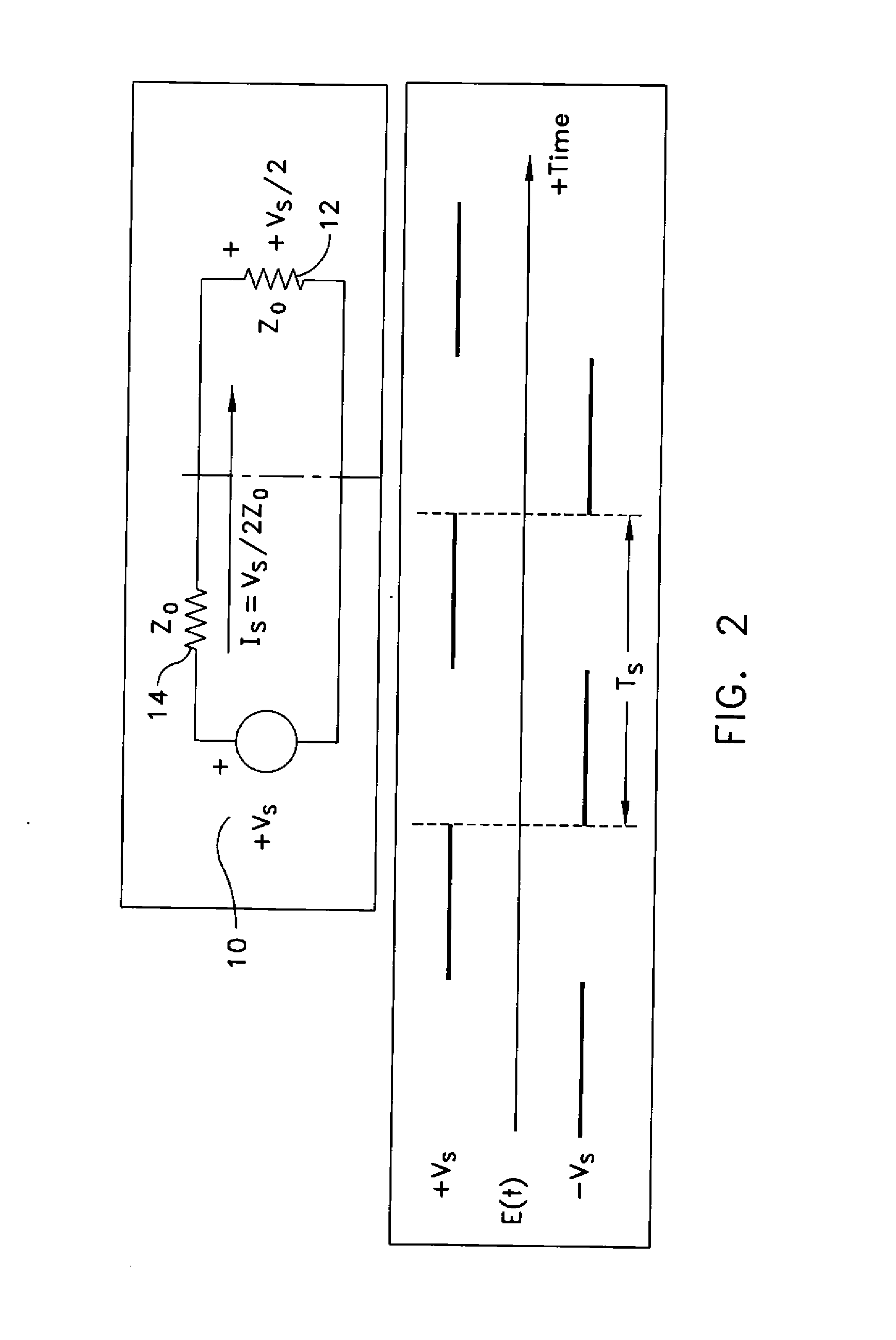
[0029]Generally, the disclosure describes a method for transmitting DC power over a uniform transmission line of any length using two circuits that work together to provide the power to loads that are remotely located with respect to the sources of the power.

[0030]The first circuit, a square-wave generator, uses a DC source to generate a square-wave. The generator uses an inductor, a capacitor, and a switch, which may be implemented using a single transistor and a drive circuit. The second circuit, a square-wave converter, converts a square-wave source into a DC source. The converter uses an inductor, a capacitor, and a P-N junction diode.

[0031]The square-wave generator and square-wave converter each provide a matched termination to a uniform transmission line so that energy is not reflected from the converter back toward the generator. Thus, the transmission line can be many wavelengths long without affecting the efficiency of power transmission. Typically, power is lost and a volt...


PUM


Abstract

A system and method is provided for coupling a power source across a rotation boundary. A generator converts a DC source on the stationary side of a rotation boundary to a square-wave at a determined frequency. The generator output connects through a transmission line and a first transformer to a set of stator rings. A set of rotor rings form a set of coupling capacitors with the stator rings. The rotor rings connect through a second transformer and a transmission line to a non-linear circuit capable of converting the square-wave to a DC voltage and current that can power a load on the rotating side of the rotating boundary in which the power is nearly equal to the power available from the source on the stationary side of the rotation boundary.

Description

STATEMENT OF GOVERNMENT INTEREST[0001]The invention described herein may be manufactured and used by or for the Government of the United States of America for governmental purposes without the payment of any royalties thereon or therefor.CROSS REFERENCE TO OTHER PATENT APPLICATIONS[0002]None.BACKGROUND OF THE INVENTION[0003](1) Field of the Invention[0004]The present invention relates to power transmission and more specifically to a method for coupling a direct current across a high-speed rotation boundary.[0005](2) Description of the Prior Art[0006]Sensor systems located at the end of towed tethers require Direct Current (DC) power for operation. Rotary joints are positioned along a tether to prevent twisting and breakage of the tether. A problem arises in connection with electronic circuits for sensing or control that are placed on a rotating platform.[0007]As such, an ongoing need exists to permit DC power to be transmitted across rotary joints and to permit signals to be sent to...

Claims


Application Information

Patent Timeline
Patent Type & Authority Applications(United States)
IPC IPC(8): H02M3/335
CPCH02J5/005H02J50/005
Inventor STEINBRECHER, DONALD H.
Owner UNITED STATES OF AMERICA
Why Eureka
Try Eureka