
Control apparatus for electric power steering apparatus

a control apparatus and electric power steering technology, applied in the direction of steering initiation, underwater equipment, instruments, etc., can solve the problems of difficult to make a hysteresis characteristic between a steering angle and a steering power equivalent, and the steering feeling cannot be improved,

Inactive Publication Date: 2009-07-30
NSK LTD
View PDF3 Cites 89 Cited by
  • Summary
  • Abstract
  • Description
  • Claims
  • Application Information

AI Technical Summary

Problems solved by technology

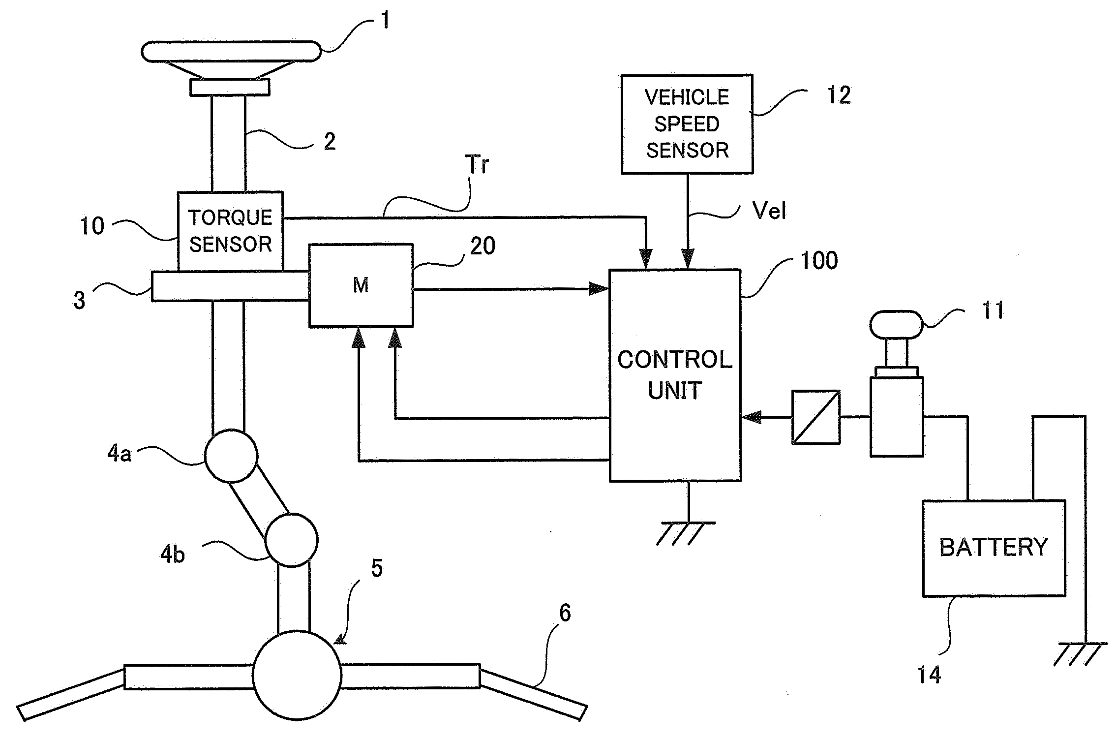
In the conventional control apparatus, however, since a reaction force at a time of a steering near a steering neutral point is small, it is difficult to accurately transmit the road information to a driver due to an influence of friction.
Further, in the conventional electric power steering apparatus, it is difficult to make a hysteresis characteristic between a steering angle and a steering power equivalent to a characteristics of a hydraulic power steering.
When the SAT information estimated by the SAT estimating feedback section 115 is directly feedbacked, the steering becomes too heavy, and thus steering feeling cannot be improved.
The estimated SAT value, however, naturally becomes a value after passing the Q filter (phase delay), and thus a delay is generated in the steering transmission system.
On the other hand, in vehicles, brake judder and shimmy which make uncomfortable to vehicle occupants occur at a time of a normal braking and a stationary traveling.
The brake judder means a floor / pedal vibration which is generated at the time of braking of vehicles, and occasionally causes the vibration to a steering rotational direction.
Further, the shimmy is vibration which is generated in the steering rotational direction when a vehicle travels, and its source is unbalance and non-uniformity of rotating portions of tire wheels.
Such the brake judder and the shimmy are not taken into consideration at all in the apparatus of Japanese Patent Laid-open No. 2002-369565 A. Japanese Patent Application Laid-open No. 2002-145075 A and Japanese Patent Application Laid-open No. 2002-161969 A disclose apparatus that attenuate vibration due to the brake judder and the shimmy, but they mechanically cope with the brake judder and the shimmy, thereby arising problems such that the cost increases and fine suppression, such as vehicle speed sensitivity, cannot be performed.
The conventional electric power steering apparatus, however, has a problem that a frictional power or the like, which corresponds to the friction of the rotor of the motor and the frictions of the vehicle and the steering system, deteriorates the returning of the steering wheel after the changing steering in a low-speed run and deteriorates an on-center feeling such as a steering wheel returning feeling and a friction feeling in a high-speed run.
Further, in a process to return to the straight run after the changing steering for the purpose of changing lanes or correcting a direction in the high-speed run (especially in a process of returning in a hand-losing state without holding the steering wheel), the wheels cannot completely return to the center position (the neutral position) even when the SAT function lets the wheels return to the neutral position.
This mainly causes deterioration in returning of the steering wheel.
This causes a drawback that performing the correction in turning and returning with a same coefficient on the basis of the road surface reaction force results in excessively heavy power in returning and turning the steering wheel during a turn at a bend in a low-speed run, which especially requires good returning of the steering wheel from a position at a large steering angle, and thereby, results in great imbalance.
The control apparatus disclosed in Japanese Patent Application Laid-open No. 2002-29441 A, however, only puts a bad returning of the steering wheel during the low speed rotation of the steering wheel in question, but does not take the SAT into account.
Accordingly, the road surface reaction force of a vehicle is so strong that the steering wheel suddenly returns excessively in some cases.
This causes a problem that a good steering feeling (especially turning and returning of a steering wheel) cannot be achieved in controlling a conventional small-sized vehicle.

Method used


Image

  • Control apparatus for electric power steering apparatus
  • Control apparatus for electric power steering apparatus
  • Control apparatus for electric power steering apparatus

Examples


first embodiment

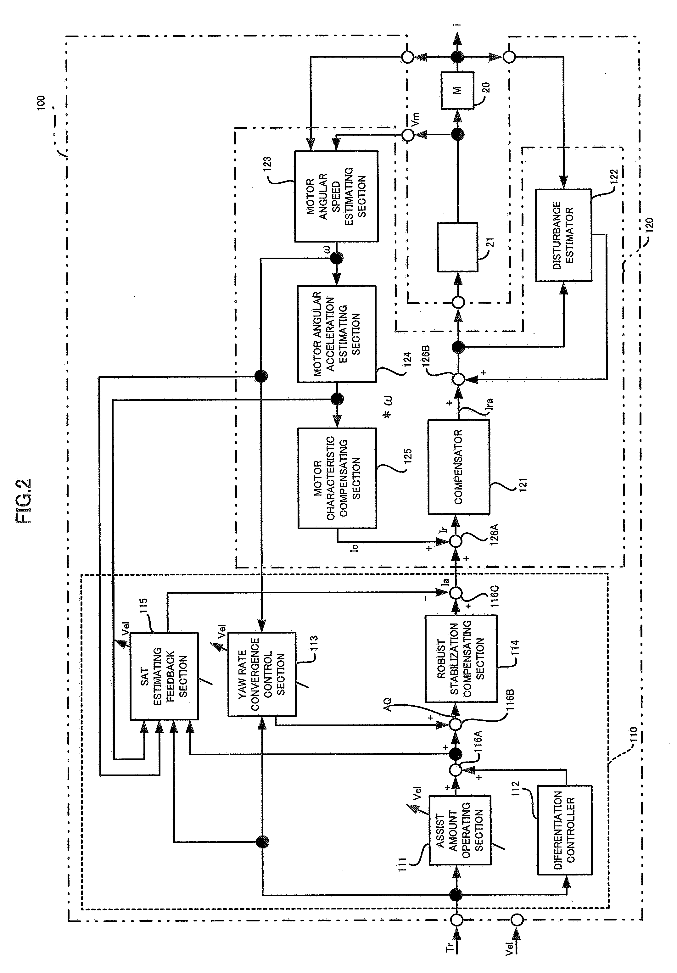
[0062]An embodiment (first embodiment) of the present invention is explained with reference to FIG. 7 related with FIG. 2. The similar or same members to those in FIG. 2 are designated by the same numbers, and the explanation thereof is omitted.

[0063]In the present invention, an SAT estimating section 117 inputs a steering torque signal Tr, an angular speed ω, an angular acceleration *ω and an added result of an adder 116A (assist amount operated result) therein so as to estimate an SAT, and feedbacks the estimated SAT value *SAT via a feedback section 118 to an adder 116C. A constitution of the feedback section 118 is as shown in FIG. 8, for example. That is to say, the feedback section 118 is composed of a phase-lead compensating section 118-1 as a phase compensating section that inputs the estimated SAT value *SAT therein so as to carry out a phase-delay compensation, a low pass filter 118-2 that eliminates the disturbance and noise, and a gain section 118-3 that multiplies a gai...

second embodiment

[0074]An embodiment (second embodiment) of the present invention is explained with reference to FIG. 10 related with FIG. 7. The similar or same members to those in FIG. 7 are designated by the same numbers, and the explanation thereof is omitted.

[0075]In the present invention, an SAT estimating section 117 inputs a steering torque signal Tr, an angular speed ω, an angular acceleration *ω and an added result in an adder 116A (assist amount operated result) therein so as to estimate the SAT, and adds the estimated SAT value *SAT via a feedback section 119 to the adder 116C. A constitution of the feedback section 119 is as shown in FIG. 11, for example. That is, the feedback section 119 is composed of a vehicle speed sensitive-type high pass filter 119-1 that inputs the estimated SAT value *SAT therein and outputs a high-frequency component, and a vehicle speed sensitive-type gain section 119-3 that multiplies a gain G. The high-pass filter 119-1 can be composed of a transfer function...

third embodiment

[0086]FIG. 13 shows an embodiment (third embodiment) of the present invention so as to correspond to FIG. 6. A steering torque value T from a torque sensor is inputted to a current command value operating section 31 and a turning / returning discriminating section 40. The vehicle speed V from the vehicle speed sensor is inputted to the current command value operating section 31. A current command value Iref operated in the current command value operating section 31 is inputted to a subtracter 43. To the turning / returning discriminating section 40, inputted is a measured or estimated angle speed ω. A discrimination signal DS discriminated in the turning / returning discriminating section 40 is inputted to a gain section 42. An SAT measured or estimated in an SAT section 41 is increased G-times (G·SAT) in the gain section 42 to be inputted to the subtracter 43. A result of the subtraction in the subtracter 43 (Iref−G·SAT) is inputted to an adder 44 as the current command value Iref. To th...


PUM


Abstract

The present invention provides a control apparatus for an electric power steering apparatus comprises: a steering assist command value calculating section; a current control section that calculates a voltage command value; and a motor driving section that drives a motor based on the voltage command value, wherein an assist power from the motor is applied to a steering system, the control apparatus is characterized in that an SAT measuring section, that inputs an angular speed and an angular acceleration of the motor, the steering assist command value and the torque signal therein so as to estimate an SAT, is provided, and the SAT obtained by the SAT measuring section is feedbacked to the steering assist command value via a feedback section composed of a phase compensating section and a gain section.

Description

TECHNICAL FIELD[0001]The present invention relates to a control apparatus for an electric power steering apparatus in which a steering assist power from a motor is applied to a steering system of an automobile or a vehicle, and particularly relates to the control apparatus for the electric power steering apparatus that executes a signal process on road information, disturbance or the like in a high frequency area so as to be capable of obtaining a safe and comfortable steering performance which provides easy tuning.[0002]Further, the present invention relates to a control apparatus for an electric power steering apparatus in which a control apparatus for an electric power steering apparatus in which a self-aligning torque (SAT) is compensated on the basis of turning and returning directions of a steering wheel.BACKGROUND ART[0003]An electric power steering apparatus, that applies an assist load to a steering apparatus of an automobile or a vehicle by means of rotational force of a m...

Claims


Application Information

Patent Timeline
Patent Type & Authority Applications(United States)
IPC IPC(8): B62D6/00
CPCB62D5/0463B62D5/0472B62D5/0466B60Y2400/307
Inventor KOBAYASHI, HIDEYUKISAKAGUCHI, TORUENDO, SHUJIKOJIMA, ATSUSHI
Owner NSK LTD
Learn More