

Substrate treatment apparatus, and substrate support to be used for the apparatus
a substrate support and treatment apparatus technology, applied in the direction of electrical devices, basic electric elements, semiconductor/solid-state device manufacturing, etc., can solve the problems of difficult spin out of etching liquid moving to the peripheral portion of the upper surface of the wafer, unfavorable in-plane uniformity, etc., to achieve the effect of improving in-plane uniformity
- Summary
- Abstract
- Description
- Claims
- Application Information
AI Technical Summary
Benefits of technology
Problems solved by technology
Method used
Image

Examples
first embodiment
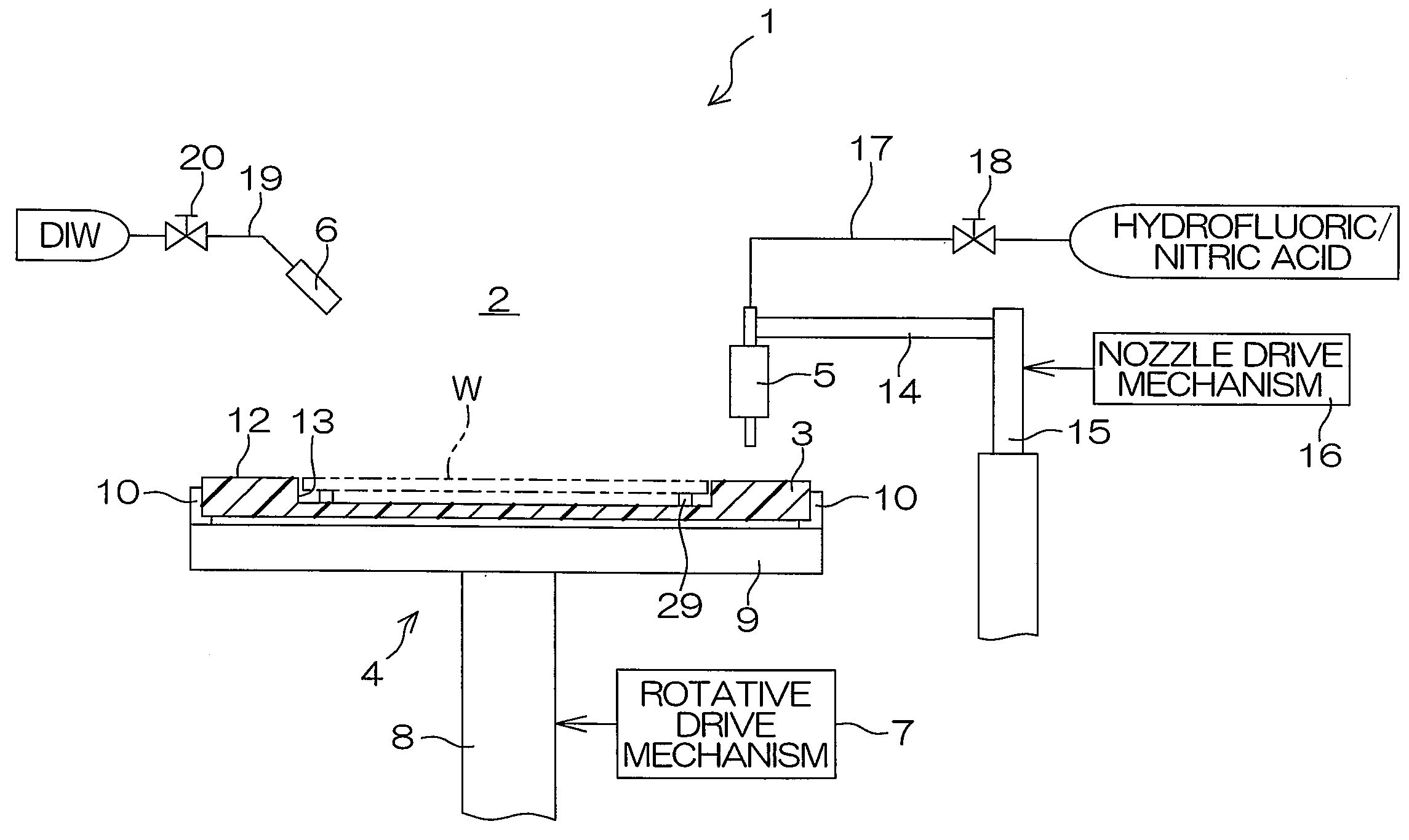
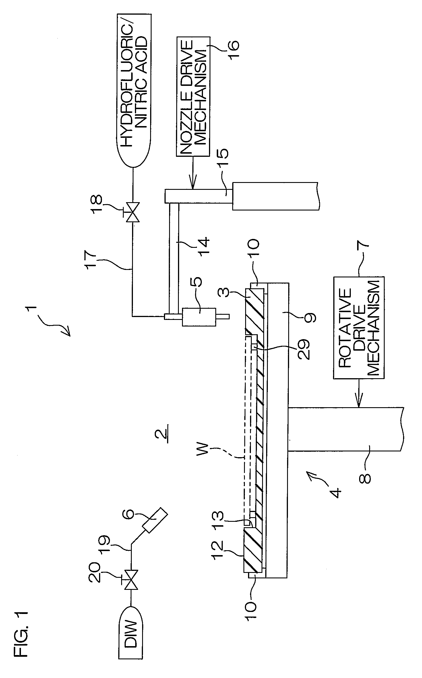
[0046]FIG. 1 is a sectional view schematically showing the construction of a substrate treatment apparatus 1 according to one embodiment (first embodiment) of the present invention.
[0047]The substrate treatment apparatus 1 is of a single substrate treatment type which performs an etching treatment on a back surface (non-device formation surface) opposite from a front surface (device formation surface) of a round wafer W such as a silicon wafer for thinning the wafer W. In this embodiment, hydrofluoric / nitric acid (a mixture of hydrofluoric acid and nitric acid) is used as an etching liquid.
[0048]The substrate treatment apparatus 1 includes a substrate support (susceptor) 3 which generally horizontally holds the wafer W with the back surface of the wafer W facing up, a spin chuck 4 which supports the substrate support 3 and serves for rotating the wafer W and the substrate support 3 about a vertical axis extending through the center of the wafer W, a hydrofluoric / nitric acid nozzle 5...
second embodiment
[0092]In the second embodiment, a slit nozzle (etching liquid supply mechanism) 61 which spouts hydrofluoric / nitric acid in the form of an elongated profile stream is used instead of the straight nozzle provided as the hydrofluoric / nitric acid nozzle 5.
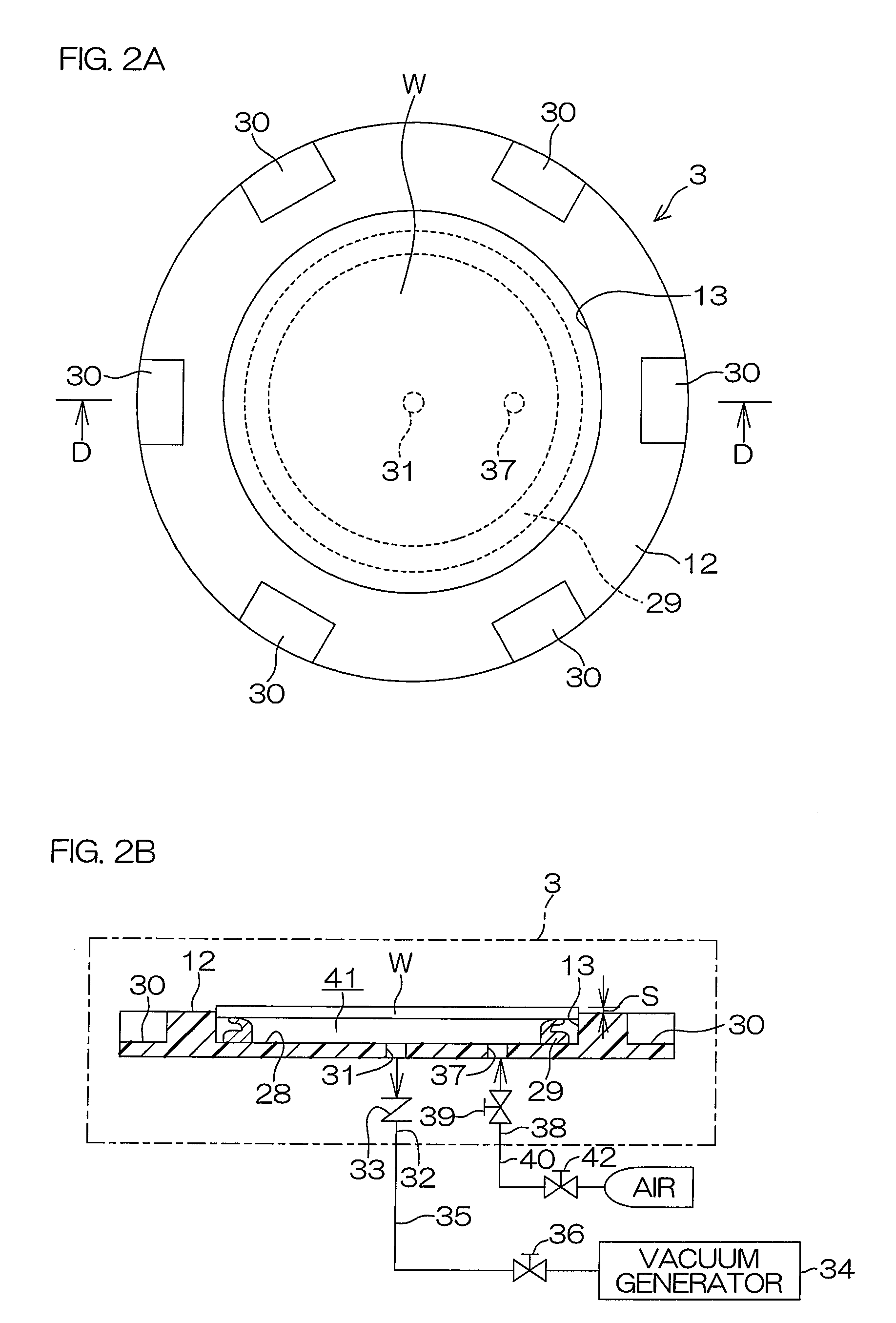
[0093]In this embodiment, a substrate support 70 including a taper surface 71 on its upper surface is employed instead of the substrate support 3 shown in FIGS. 2A and 2B. In other words, the substrate holding mechanism consists of the substrate support 70 and spin chuck 4.
[0094]The slit nozzle 61 includes a slit spout 63 which is an opening linearly extending along a predefined Y-axis and opposed to the upper surface of the wafer W held by the substrate support 70. The slit nozzle 61 is supported slidably along an X-axis perpendicular to the Y-axis by a support rail (not shown) The X-axis and the Y-axis extend parallel to the upper surface of the wafer W (horizontally). A slit nozzle drive mechanism 64 is connected to the slit nozzle...
fourth embodiment
[0138]Next, an exemplary wafer treatment to be performed by the substrate treatment apparatus 100 will be described.
[0139]For the wafer treatment, the controller 95 drives the lift-pin lift drive mechanism 108 to move up the lift pins 102 to the projecting position before an untreated wafer W is transported into the treatment chamber 2 (before Step S11 in FIG. 11). Thereafter, the untreated wafer W is transported into the treatment chamber 2 by the transport robot (not shown), and rested on the lift pins 102. Then, the controller 95 drives the lift-pin lift drive mechanism 108 to move the lift pins 102 down to the retracted position. Thus, the wafer W is accommodated in the accommodation recess 84. In this manner, the wafer W is transferred to the spin base 82 (a step corresponding to Step S11 in FIG. 11).
[0140]When the controller 95 closes the relief valve 93 and opens the suction valve 90 with the vacuum generator 87 being active, air is sucked from the space 94 and the spaces 10...
PUM
| Property | Measurement | Unit |
|---|---|---|
| Height | aaaaa | aaaaa |
| Affinity | aaaaa | aaaaa |
Abstract
Description
Claims
Application Information