Heating element using carbon NANO tube

a technology of carbon nanotubes and heating elements, applied in the direction of heating element materials, ohmic resistance heating, electrical appliances, etc., can solve the problems of reducing the life of equipment, difficult control of temperature, and increasing so as to reduce the overall manufacturing time, reduce the cost of equipment investment, and improve the effect of heating efficiency

Inactive Publication Date: 2009-08-06
EXAENC CORP
View PDF6 Cites 96 Cited by
  • Summary
  • Abstract
  • Description
  • Claims
  • Application Information

AI Technical Summary

Benefits of technology

[0020]As described above, according to the present invention, the can be manufactured in a simple process of coating a heat-resistant member with carbon nanotube, relatively reduce the overall manufacturing time, easily change the shape and specifications, and have a heating efficiency higher than that of a heating element having a different shape and material. Thus, the heat element having a high quality at a low investment cost is provided so that the productivity and quality can be improved.
[0021]Also, since carbon nanotube in a water-dispersive state is used instead of an organic binder in coating the carbon nanotube with a heat-resistant element,

Problems solved by technology

Also, as the time passes, the nichrome wire gradually becomes thinner due to the oxidation reaction so that the control of temperature is difficult and the life span thereof is shortened.
However, in the conventional heating element using the ceramic slurry, since a separate dedicated equipment is needed to press the green sheet, a considerable equipment investment cost is needed.
Also, in the curing process, since the volume is contracted by about 15%, an accurate specifications control is difficult.
Further, in the curing process, since a large amount of a crystallizer included in the green sheet remains as residual carbon due to incomplete combustion, the electricity-resistant and voltage-resistant characteristics are critically damaged.
In the conventional heating elements, the overall manufacturing time is excessively consumed, the manufacturing process is complicated, the change of the shape and specifications is not easy, and the investment cost is high so that the productivity and quality of the heating elements are deteriorated.

Method used


Image

  • Heating element using carbon NANO tube
  • Heating element using carbon NANO tube
  • Heating element using carbon NANO tube

Examples


embodiment 1

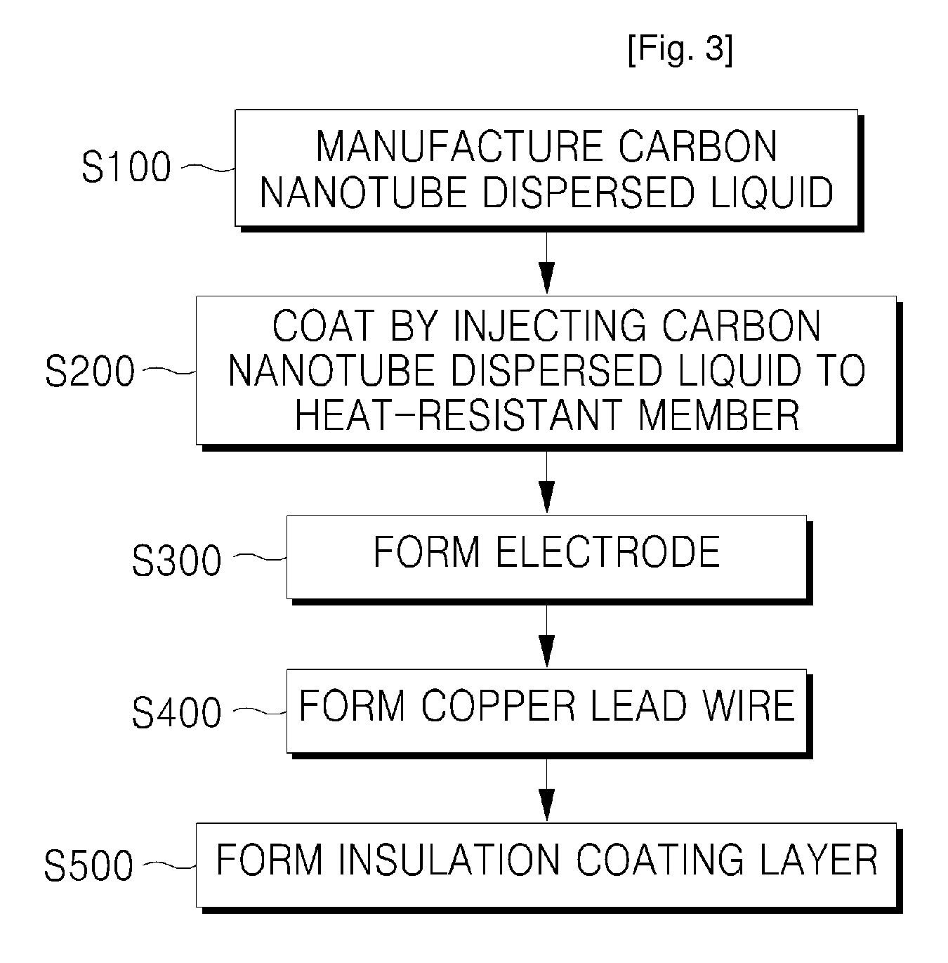
[0045]A ceramic substrate is used as the heat-resistant member 11 and water-dispersive carbon nanotube is coated in a spray method. When the surface resistance is set to 946Ω and applied voltage is set to 132V and 220V, the heating temperatures of the surface measured in these conditions are respectively 282° C. and 409° C.

embodiment 2

[0046]A ceramic substrate is used as the heat-resistant member 11 and water-dispersive carbon nanotube is coated in a spray method. When the surface resistance is set to 1129Ω and applied voltage is set to 132V and 220V, the heating temperatures of the surface measured in these conditions are respectively 210° C. and 328° C.

embodiment 3

[0047]A ceramic substrate is used as the heat-resistant member 11 and water-dispersive carbon nanotube is coated in a spray method. When the surface resistance is set to 1274Ω and applied voltage is set to 132V and 220V, the heating temperatures of the surface measured in these conditions are respectively 192° C. and 298° C.


PUM

PropertyMeasurementUnit
temperaturesaaaaaaaaaa
temperatureaaaaaaaaaa

Abstract

Provided is a heating element using carbon nanotube including a heat-resistant member having a heat-resistant characteristic, a carbon nanotube coating layer formed on at least one surface of the heat-resistant member, and a pair of electrodes electrically connected to the carbon nanotube coating layer and inducing heating of the carbon nanotube coating layer when connected to power. The manufactured in a simple process of coating a heat-resistant member with carbon nanotube, relatively reduce the overall manufacturing time, easily change the shape and specifications, and have a heating efficiency higher than that of a heating element having a different shape and material.

Description

TECHNICAL FIELD[0001]The present invention relates to a heating element using carbon nanotube, and more particularly, to a heating element using carbon nanotube which can be manufactured in a simple process of coating a heat-resistant member with carbon nanotube and have a heating efficiency higher than that of a heating element having a different shape and material.BACKGROUND ART[0002]In general, a heating element is a material that converts electric energy to heat energy and transfers energy by radiating the heat to the outside. The heating element is widely used for various home appliances or throughout general industrial fields.[0003]The heating element can be classified into metal heating elements, nonmetal heating elements, and other heating elements according to the materials thereof. The metal heating element which forms a main stream of the initial heating elements includes Fe—Cr—Al based materials, Ni—Cr based materials, and high melting point metals (platinum, Mo, W, and ...

Claims


Application Information

Patent Timeline
Patent Type & Authority Applications(United States)
IPC IPC(8): H05B3/14
CPCH05B3/145H05B2214/04H05B3/265
Inventor LEE, TAEK SOOSEO, CHANG WOOKANG, SEUNG KYUNG
Owner EXAENC CORP
Why Eureka
Try Eureka