Rear vehicle body structure

a rear vehicle and body technology, applied in the direction of roofs, vehicle arrangements, transportation and packaging, etc., can solve the problems of limited rear end of spare tires, ineffective utilization, and limited ability of rear vehicle bodies to effectively absorb impact energy at the time of rear ends, etc., to achieve increased rigidity and energy absorption capability, increase compression stroke, and increase the effect of energy absorption

Inactive Publication Date: 2009-08-06
HONDA MOTOR CO LTD
View PDF3 Cites 19 Cited by
  • Summary
  • Abstract
  • Description
  • Claims
  • Application Information

AI Technical Summary

Benefits of technology

[0013]According to this arrangement, at the time of a rear end collision, the spare tire pan is pushed forward by the rear end cross member. The rear end cross member enables the impact load to be evenly distributed to the spare tire pan or the rear floor panel. Because the spare tire is stored in a slanted orientation, such an impact causes the spare tire to be raised at the rear end while the spare tire pan undergoes a buckling or other compressive deformation. Thereby, the rear vehicle body structure provides a significant deformation stroke at the time of a rear end collision, and this increases the capability of the rear vehicle body to absorb impact energy. This is particularly beneficial for a hatchback passenger vehicle in which the passenger compartment directly communicates with the luggage compartment in the rear, and the rear seats are located at a short distance from the rear end of the vehicle body.
[0014]Furthermore, the spare tire can be raised into an upright posture in a reliable manner at the time of a rear end collision, and this prevents the intrusion of the spare tire into the passenger compartment and protects the rear seats from the impact even when the subject vehicle is hit from behind by a tall vehicle.
[0015]Because the torsion beam of the suspension system is received in the slot formed in the floor of the vehicle body, the torsion beam is effectively utilized for reinforcing the rear vehicle body against the impact of the rear end collision, and this increases the compression stroke and hence the energy absorbing capability of the rear vehicle body. This effect is particularly enhanced if a spare tire bumper is attached to a front side of the vertica...

Problems solved by technology

If the rear vehicle body structure is configured to drop the rear end of a spare tire at the time of a rear end collision as proposed in Japanese patent No. 3620288, the deformation of the spare tire pan cannot be effectively utilized for the absorption of the impact energy of a rear end collision, and this limits the capability of the rear vehicle body to effectively absorb the impact energy at the time of a rear end collision.
However, because the front vertical wall of the spare tire pan hangs over the front part of the spare tire, the spare tire is caught by this overhang as the rear end thereof is raised due to the impact of a rear end collision, and the rear end of the spare tire can be raised only to a limited extent.
Therefore, the deformation stroke of the rear vehicle body is limited by such a behavior of the spare tire at the time of a rear end collision.
Also, because of the absence of a cross member that connects the rear frames with each other, the impact of an offset rear end collision is not favorably distributed to the rear vehicle body...

Method used


Image

  • Rear vehicle body structure
  • Rear vehicle body structure
  • Rear vehicle body structure

Examples


Embodiment Construction

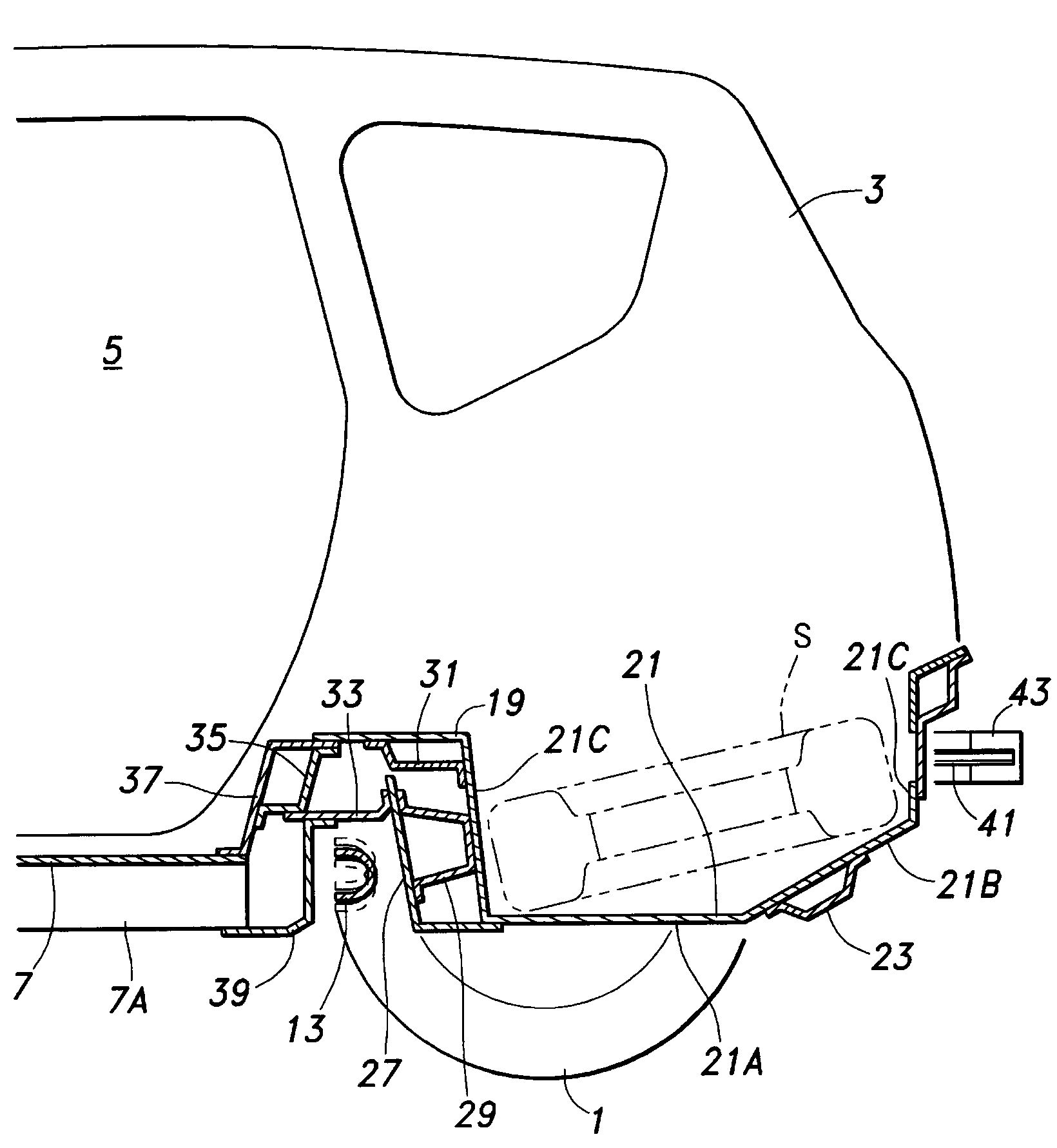
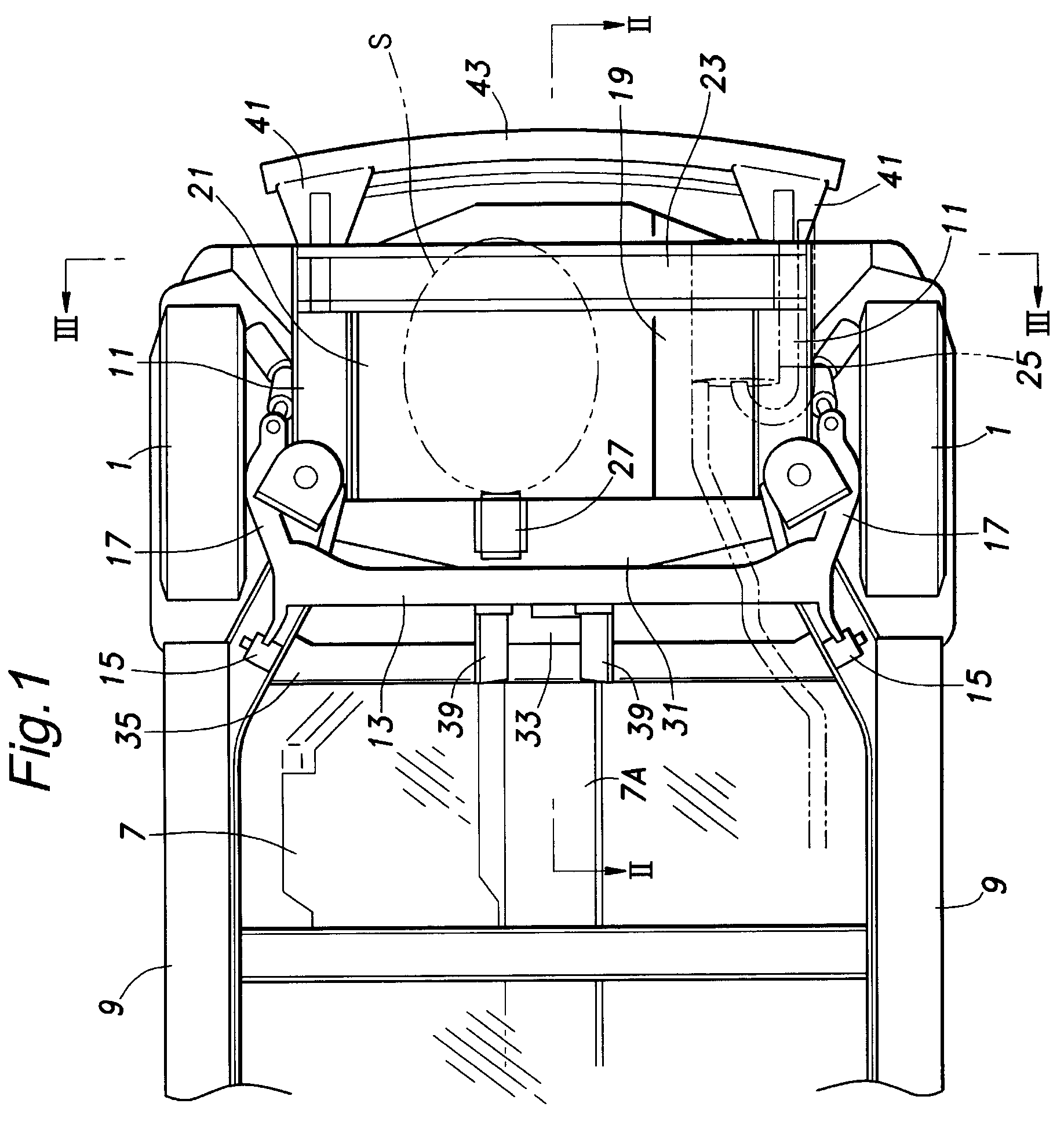
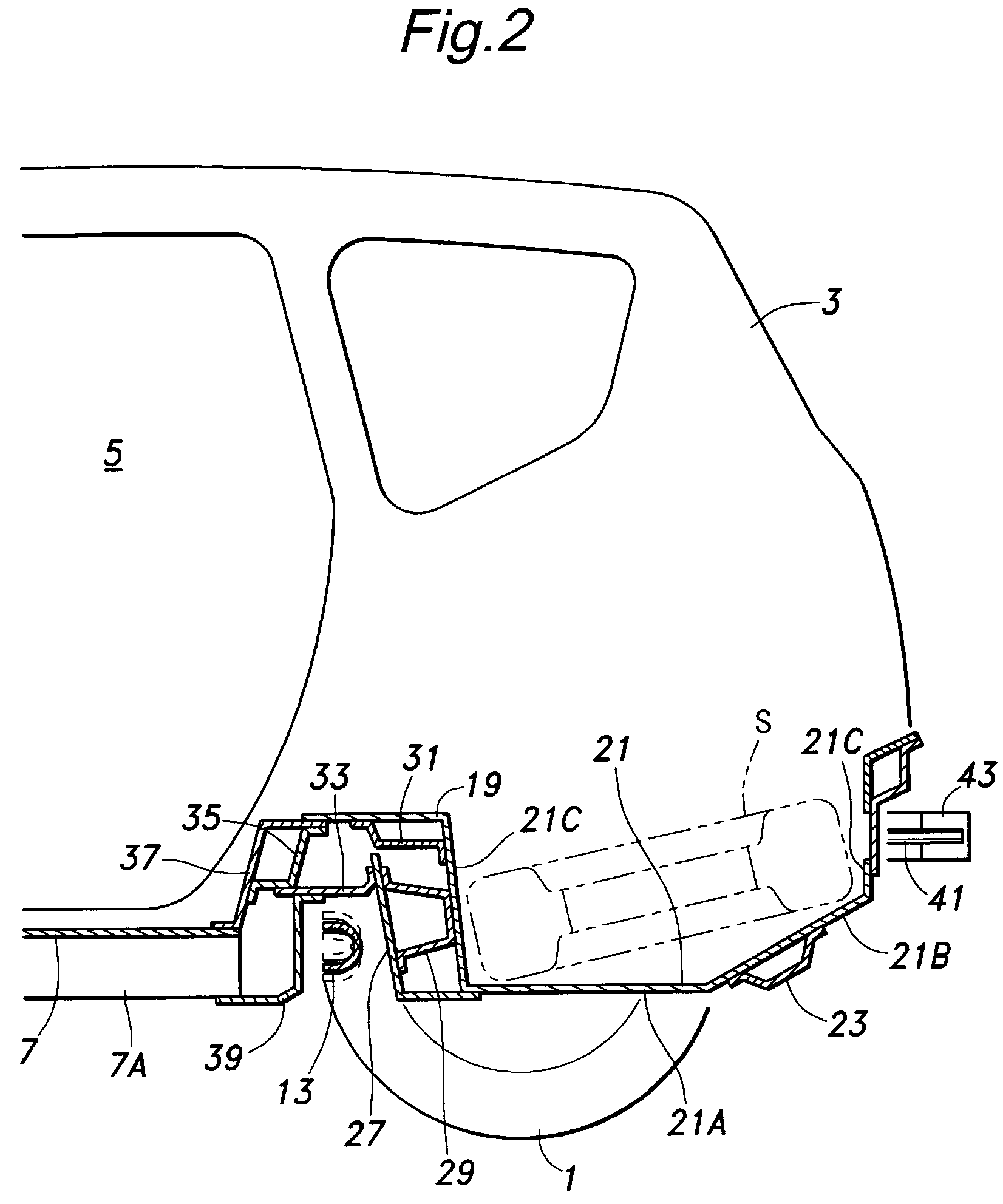
[0022]FIGS. 1 to 3 show a hatchback passenger vehicle having a rear vehicle body structure embodying the present invention. These drawings show a pair of rear tires 1, a pair of side panels 3, a pair of rear side door openings 5 each defined in the corresponding side panel 3, a front floor panel 7 including a floor tunnel 7A extending centrally in the longitudinal direction and a pair of side sills 9 attached to either side edge of the front floor panel 7.

[0023]In the rear part of the vehicle body is provided a pair of rear side frames 11 extending in continuation from the rear ends of the corresponding side sills 9. In the illustrated embodiment, the front end of each rear side frame 11 extends obliquely so that the rear parts of the rear side frames 11 extend parallel to each other with a smaller spacing between them than the side sills 9. Each rear side frame 11 supports a corresponding pivot assembly 15 which is incorporated with a rubber bush and pivotally supports a base end o...


PUM


Abstract

The following abstract will replace all prior versions of the abstract in the application:
In a rear vehicle body structure for a vehicle using a torsion beam suspension system, a laterally extending slot is defined between a vertical front wall of a spare tire pan defined in a rear floor panel and a raised rear end of a front floor panel, and a torsion beam of the torsion beam suspension system is received in this slot. The spare tire is received in the spare tire pan in a rear end up slanted orientation. A rear end cross member extends across the vehicle in a rear end of the spare tire pan. In a rear end collision, the spare tire pan is pushed forward by the rear end cross member. The rear end cross member enables the impact load to be evenly distributed to the spare tire pan or the rear floor panel.

Description

TECHNICAL FIELD[0001]The present invention relates to a rear vehicle body structure configured to mount a torsion beam type wheel suspension system, and in particular to a rear vehicle body structure which is favorably reinforced against a rear end collision.BACKGROUND OF THE INVENTION[0002]There have been proposed a number of rear vehicle body structures that are reinforced against a rear end collision. In the rear vehicle body structure disclosed in Japanese patent No. 3620288, a deformation resisting portion having a relatively high rigidity is formed by a pair of rear side members, a suspension supporting cross member, a cross member for retaining a rear seat bottom and a rear floor panel, and a deformation permitting portion having a relatively low rigidity is formed between the deformation resisting portion and a spare tire pan for receiving a spare tire. Thereby, the impact of a rear end collision is made to cause a deformation of the deformation permitting portion in such a ...

Claims


Application Information

Patent Timeline
IPC IPC(8): B62D21/00
CPCB62D43/10B62D25/2027
Inventor YAMAGUCHI, TOSHIZUMINUSHII, HIROTSUYUZAKI, TAKUMI
Owner HONDA MOTOR CO LTD
Why Eureka
Try Eureka