Power Tool Having Motor Speed Monitor

a technology of motor speed and monitor, which is applied in the direction of motor/generator/converter stopper, dynamo-electric converter control, instruments, etc., can solve the problems of affecting the efficiency of the power tool, overheating of the motor during operation, etc., and achieves the effect of protecting from overheating, reducing the number of power tools, and relatively constant rotational speed of the motor

Inactive Publication Date: 2009-08-06
BLACK & DECKER INC
View PDF5 Cites 37 Cited by
  • Summary
  • Abstract
  • Description
  • Claims
  • Application Information

AI Technical Summary

Benefits of technology

[0005]According to the present invention there is provided a power tool comprising a housing, an electric motor within the housing for driving an output of the tool, a vibration transducer for sensing vibrations generated by the motor and producing a vibration signal dependent upon the sensed vibrations, a controller for controlling the rotational speed of the motor, and a signal processor for receiving the vibration signal from the vibration transducer, determining the rotational speed of the motor based on the vibration signal, and providing an output signal to the controller to cause the controller to control the rotational speed of the motor.
[0006]By providing a signal processor for receiving the vibration signal from the vibration transducer, determining the rotational speed of the motor based on the vibration signal, and providing an output signal to the controller to cause the controller to control the rotational speed of the motor, this provides the advantage of enabling the rotational speed of the motor to be kept relatively constant, irrespective of the resistance caused by the work material during operation. This maximises, for example, the cutting efficiency of the power to

Problems solved by technology

When the power tool is in use, the resistance of the work material to the cutting action of the tool bit varies, which can cause unpredictable variations of the rotational s

Method used


Image

  • Power Tool Having Motor Speed Monitor
  • Power Tool Having Motor Speed Monitor
  • Power Tool Having Motor Speed Monitor

Examples


Embodiment Construction

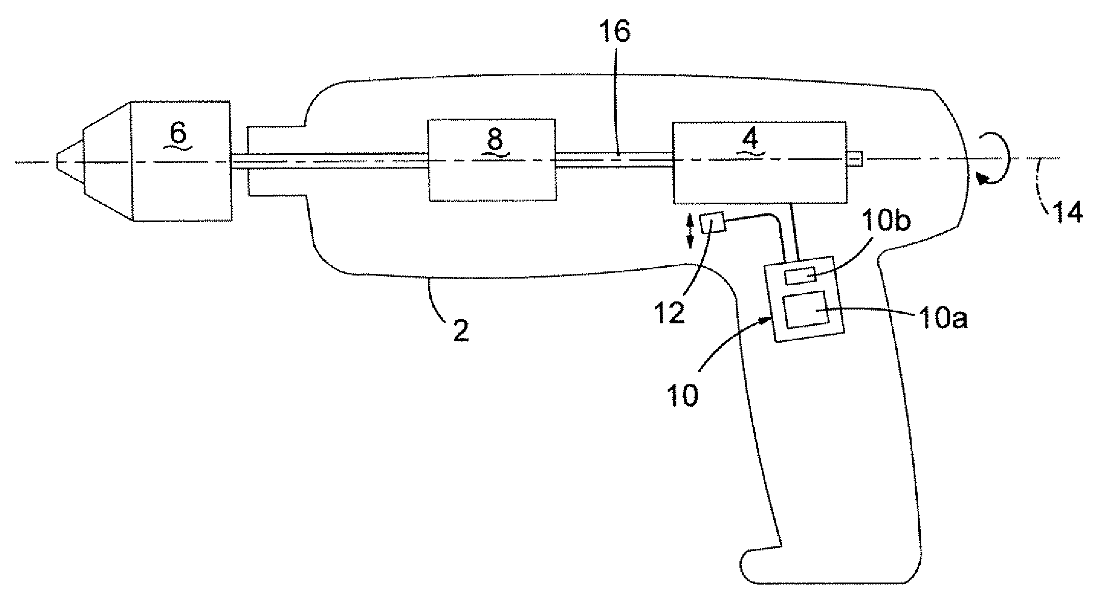
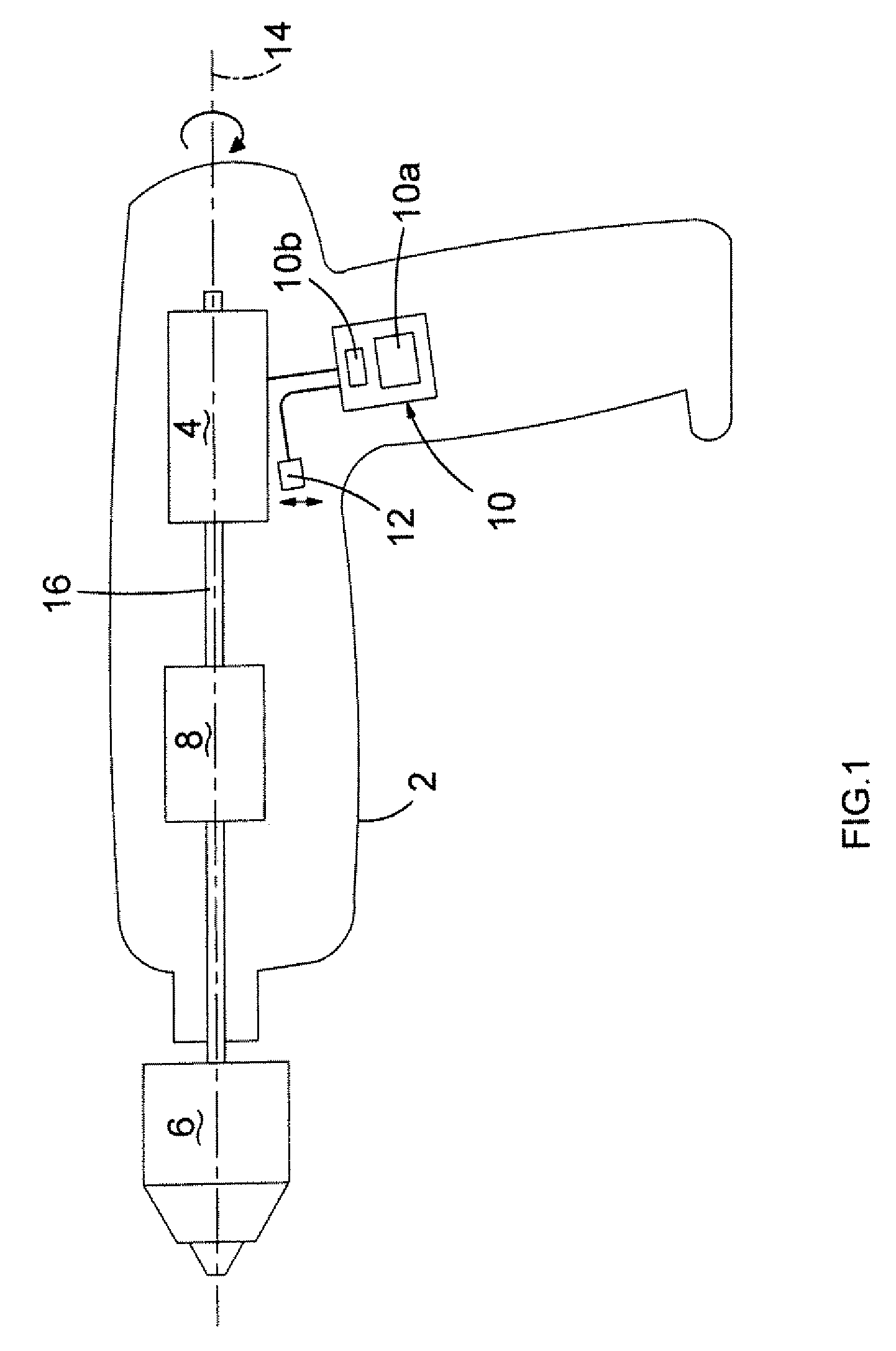
[0019]Referring to FIG. 1, a hammer drill comprises a body 2 in which is mounted a motor 4. The motor 4 rotatingly drives a chuck 6, for receiving a drill bit (not shown), via a gearbox 8. The rotational speed of the motor 4 is controlled by an electronic module 10 comprising a controller 10a and a signal processor 10b, the function of which will be described in greater detail below.

[0020]A vibration transducer 12 is mounted on the body 2 near the motor 4 but not on the axis of rotation 14 of the spindle 16 of the motor 4. The vibration transducer 12 can be any type of sensor, for example, a piezo-electric sensor, but must be capable of detecting vibrations over a range of frequencies. The vibration transducer 12 measures the amplitude of the vibration caused by the motor 4 in a radial direction from the axis of rotation 14 of the spindle 16.

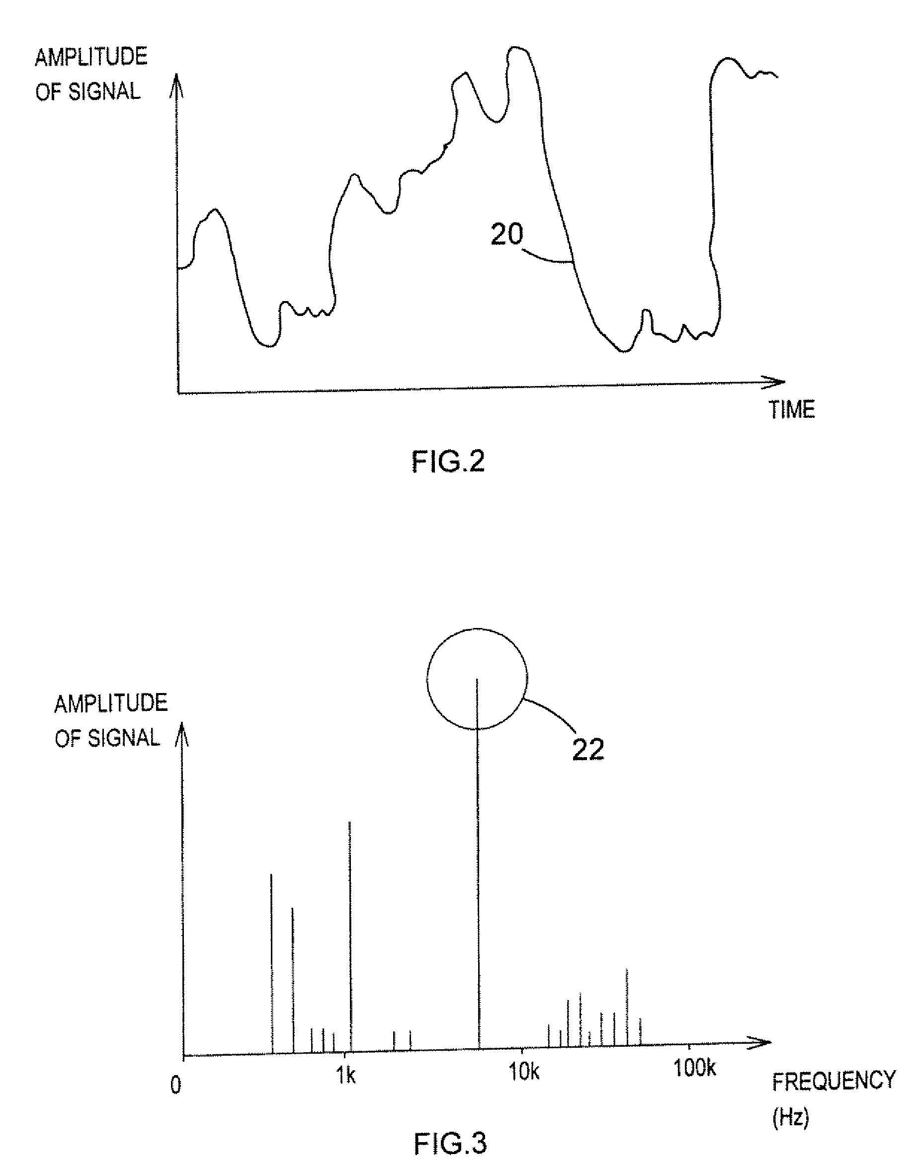
[0021]FIG. 2 shows a graph of a typical vibration signal 20 produced by the vibration transducer 12 when the hammer drill is operating, the gra...


PUM


Abstract

A hammer drill comprising a body (2) containing an electric motor (4) for driving an output (6) of the drill is disclosed. A vibration transducer (12) senses vibrations generated by the motor and produces a vibration signal dependent upon the sensed vibrations. An electronic module (10) includes a controller (10a) for controlling the rotational speed of the motor, and a signal processor (10b) for receiving the vibration signal from the vibration transducer, determining the rotational speed of the motor based on the vibration signal, and providing an output signal to the controller to cause the controller to control the rotational speed of the motor.

Description

FIELD OF THE INVENTION[0001]The present invention relates to portable power tools, and relates particularly to a portable power tool having means for detecting and controlling the speed of rotation of the motor of the portable power tool.BACKGROUND OF THE INVENTION[0002]Power tools such as hammer drills are well known in the art and are generally provided with an electric motor driving a spindle for receiving the shank of a tool or bit such as a drill bit or a chisel bit. Such hammer drills comprise an impact mechanism that converts the rotational drive from the motor to a reciprocating drive causing a piston to reciprocate within the spindle. The piston reciprocatingly drives a ram by means of a closed air cushion located between the piston and the ram, and the impacts from the ram are then transmitted to the tool or bit of the hammer. The rotational movement of the motor and the reciprocating piston cause vibrations having various superimposed frequencies that are transmitted thro...

Claims


Application Information

Patent Timeline
IPC IPC(8): H02P7/28H02K7/14
CPCB25D11/00G01H1/003B25D2250/221B25D2250/201
Inventor GUMPERT, RENE
Owner BLACK & DECKER INC
Why Eureka
Try Eureka