Endfire antenna apparatus with multilayer loading structures

a technology of loading structure and antenna, applied in the field of antenna, can solve the problems of limiting the obtaining of high gain, adopting conventional antenna design techniques, etc., and achieves the effects of reducing the length of the dielectric transmission substrate, high gain, and high gain characteristics

Active Publication Date: 2009-08-06
PANASONIC INTELLECTUAL PROPERTY CORP OF AMERICA
View PDF2 Cites 13 Cited by
  • Summary
  • Abstract
  • Description
  • Claims
  • Application Information

AI Technical Summary

Benefits of technology

[0016]As described above, it is difficult to adopt conventional antenna design techniques under the condition of a reduced length of a dielectric substrate, and thus, there is a limit to obtaining a high gain. Therefore, an object of the present invention is to overcome this problem, and to provide a small endfire antenna apparatus capable of achieving high gain characteristics even under the condition of a reduced length of a dielectric substrate.
[0026]The endfire antenna apparatus of the present invention can achieve high gain characteristics with a small antenna structure in which the length of a dielectric transmission substrate is reduced as compared to conventional arts. According to the endfire antenna apparatus of the present invention, it is possible to obtain a high gain without increasing the area occupied by a circuit of the dielectric transmission substrate. Alternatively, according to the endfire antenna apparatus of the present invention, it is possible to reduce the area of an antenna unit, which cannot be achieved by conventional antenna design techniques.

Problems solved by technology

As described above, it is difficult to adopt conventional antenna design techniques under the condition of a reduced length of a dielectric substrate, and thus, there is a limit to obtaining a high gain.

Method used


Image

  • Endfire antenna apparatus with multilayer loading structures
  • Endfire antenna apparatus with multilayer loading structures
  • Endfire antenna apparatus with multilayer loading structures

Examples


first preferred embodiment

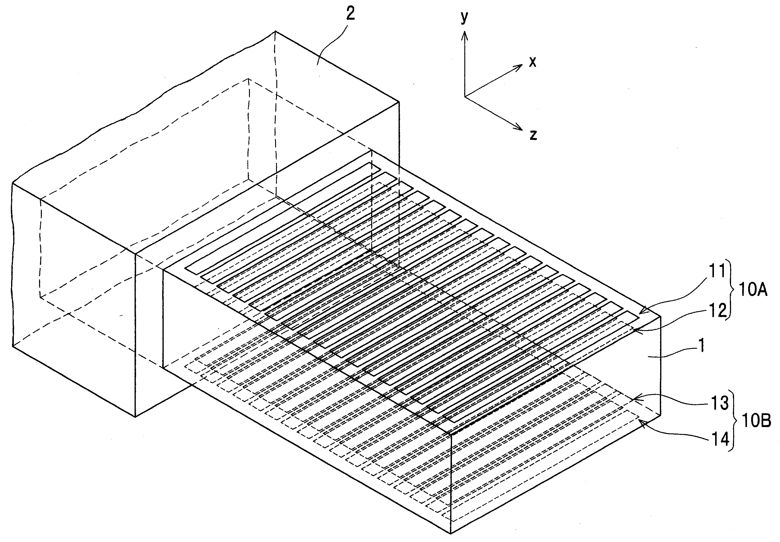
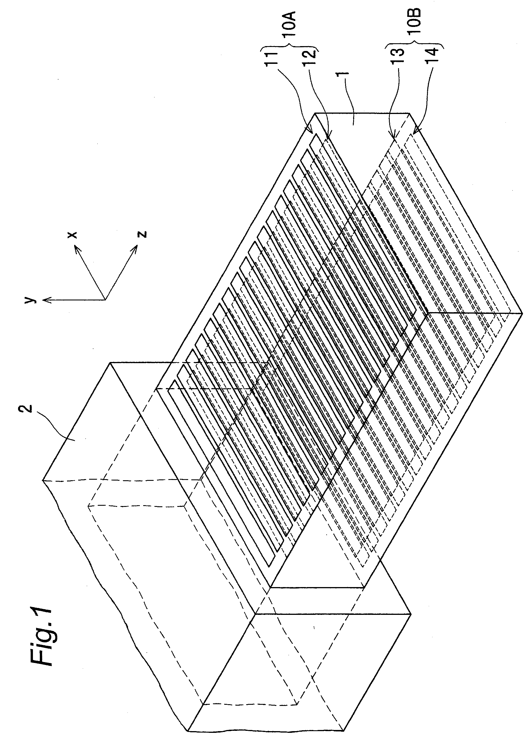
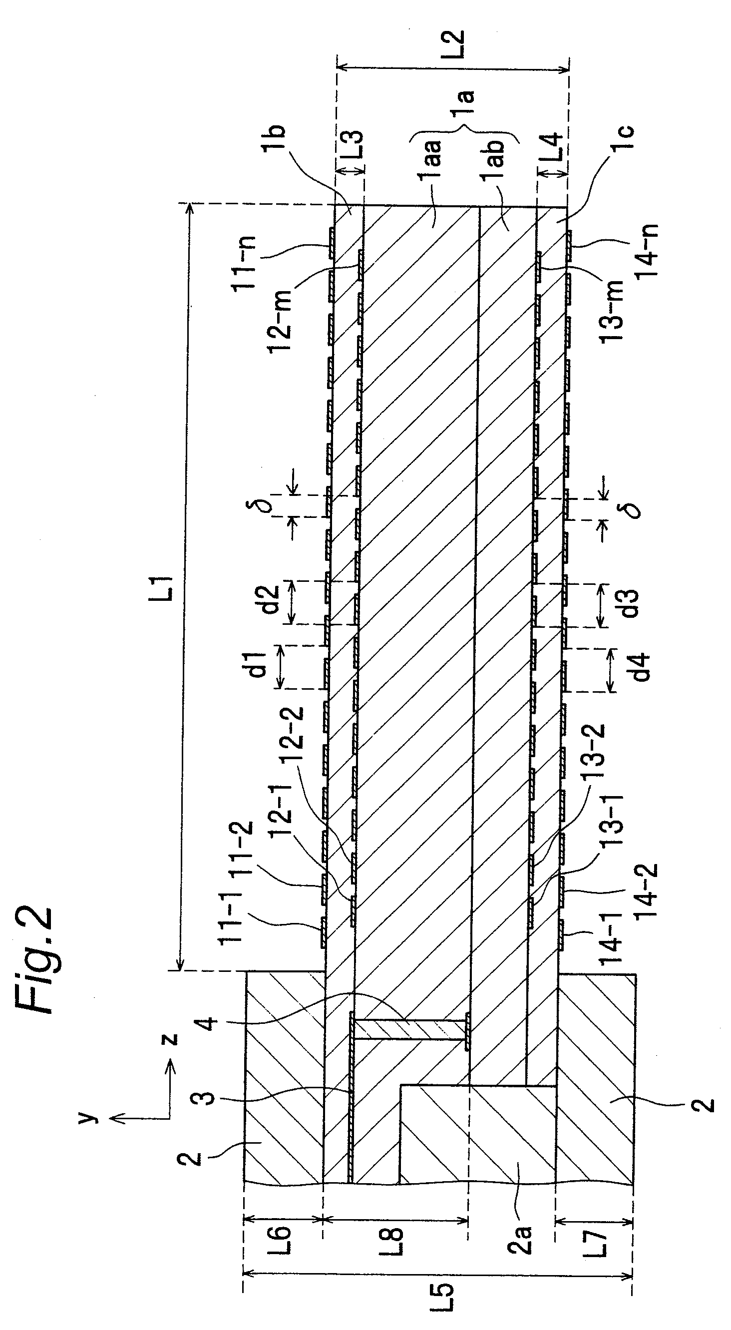
[0044]FIG. 1 shows a perspective view of a configuration of an endfire antenna apparatus according to a first preferred embodiment of the present invention, partially shown in a transparent view. FIG. 2 shows a yz-plane central cross-sectional view of the endfire antenna apparatus in FIG. 1. FIG. 3 shows a front view of the endfire antenna apparatus in FIG. 1 from +z direction. The endfire antenna apparatus of the present preferred embodiment is an antenna that is provided with a dielectric transmission substrate 1 extending in a transmission direction, i.e., z-axis direction in FIG. 1, and a plurality of conductive strip elements provided to the dielectric transmission substrate 1 to be orthogonal to the z-axis direction, and that transmits an electromagnetic wave in the z-axis direction inside the dielectric transmission substrate 1 and along its surfaces, to radiate the electromagnetic wave from an end face in +z direction of the dielectric transmission substrate 1 (open end face...

second preferred embodiment

[0058]FIG. 6 shows a perspective view of a configuration of an endfire antenna apparatus according to a second preferred embodiment of the present invention, partially shown in a transparent view. FIG. 7 shows a yz-plane cross-sectional view of the endfire antenna apparatus in FIG. 6. In FIGS. 6 and 7, detailed configurations of a dielectric transmission substrate 1 and a feed circuit are omitted, because they are the same as those in the first preferred embodiment. The endfire antenna apparatus of the present preferred embodiment is characterized by including a removed region 22 which is a continuous region without placing conductive strip elements, in part of the region-for-placement of the multilayer loading structures. As shown in FIG. 7, in a non-shielded region of the dielectric transmission substrate 1 with a region length L1 (i.e., the region-for-placement of multilayer loading structures 10A and 10B), each of the multilayer loading structures 10A and 10B on a top side and a...

third preferred embodiment

[0062]FIG. 8 shows a perspective view of a configuration of an endfire antenna apparatus according to a third preferred embodiment of the present invention, partially shown in a transparent view. In the endfire antenna apparatus according to the preferred embodiment of the present invention, conductive strip elements composing multilayer loading structures 10A and 10B are not necessarily formed over the entire length in a width direction of a dielectric transmission substrate 1. The endfire antenna apparatus of the present preferred embodiment is characterized by including conductive strip groups 11A and 11B, 12A and 12B, 13A and 13B, and 14A and 14B, which are configured by dividing into two parts the conductive strip groups 11, 12, 13, and 14 of the endfire antenna apparatus of the first preferred embodiment, at the center in the width direction (x-axis direction). Even when the conductive strip elements of all conductive strip groups in the endfire antenna apparatus are thus divi...


PUM


Abstract

A plurality of conductive strip elements compose multilayer loading structures on top and bottom surfaces of a dielectric transmission substrate, by which a part of intra-substrate transmission components of a electromagnetic wave are leaked out of the surfaces. Each multilayer loading structure includes a first conductive strip group of conductive strip elements within a first plane, and a second conductive strip group of conductive strip elements within a second plane, and the first and second conductive strip groups are formed to be capacitively coupled to each other. In each of the first and second conductive strip groups, the conductive strip elements are placed at intervals of a distance of a quarter or less of a reference adjacent distance, where the reference adjacent distance is defined as a distance for generating spatial harmonics of the electromagnetic wave on the surfaces of the dielectric transmission substrate.

Description

BACKGROUND OF THE INVENTION[0001]1. Field of the Invention[0002]The present invention relates to an antenna for transmitting and receiving analog or digital radio frequency signals in a frequency band of the microwave band or higher, mainly in a frequency band of the millimeter-wave band. More particularly, the present invention relates to an endfire antenna apparatus, efficiently radiating in a direction parallel to a substrate that is provided with a plurality of conductive elements composing the antenna.[0003]2. Description of the Related Art[0004]In recent years, it has been considered to adopt millimeter-wave radio techniques not only to an onboard radar for cars, but also to a wireless LAN (Local Area Network) and a wireless PAN (Personal Area Network). In order to provide a small-sized terminal with a millimeter-wave radio unit, it is essential to reduce the antenna size, i.e., to reduce the thickness of a circuit board including the antenna unit, and to reduce the area of th...

Claims


Application Information

Patent Timeline
Patent Type & Authority Applications(United States)
IPC IPC(8): H01Q1/38H01Q13/00
CPCH01Q1/243H01Q13/28H01Q1/38
Inventor KANNO, HIROSHI
Owner PANASONIC INTELLECTUAL PROPERTY CORP OF AMERICA
Why Eureka
Try Eureka