Virtual computing infrastructure

a virtual computing and infrastructure technology, applied in the field of virtual computing infrastructure, can solve the problems of difficult management of physical it (information technology) infrastructure, difficult manual changes, high cost and error prone, etc., and achieve the effect of less hardware cost, simple arrangement, and more separation

Inactive Publication Date: 2009-08-06
HEWLETT PACKARD DEV CO LP
View PDF17 Cites 416 Cited by
  • Summary
  • Abstract
  • Description
  • Claims
  • Application Information

AI Technical Summary

Benefits of technology

[0011]The use of a virtual overlay infrastructure provides independence from the underlying physical configuration, which has advantages for upgradeability, for physical resource utilization, reconfigurability, performance of the applications and for security. This can overcome some of the disadvantages of the known arrangements which virtualize only some of the entities. The mapping being altered dynamically has a number of advantages over a predetermined mapping. It can be optimized as business priorities change, or as conditions of the underlying physical resources change for example. An additional feature for dependent claims is a number of separate virtual overlay infrastructures each isolated from others, but sharing common physical resources. Another additional feature is the mapping manager being arranged to alter the mapping according to a policy on availability. This can help ensure the mapping does not leave critical applications dependent on a physical resource with a single point of failure for example. The policy could specify that a back up virtual entity is mapped to a different physical identity, to ensure a given standard of availability.
[0047]Another such additional feature is the user accessible part having access to some or all of the virtual network entities in the infrastructure. This can assist in debugging and testing by users.

Problems solved by technology

Physical IT (information technology) infrastructures are difficult to manage.
Changing the network configuration, adding a new machine or storage device are typically difficult manual tasks.
This makes such changes expensive and error prone.
It also means that the change can take several hours or days to take place, limiting the rate at which reconfiguration can take place to take account of changing business demands.
Sometimes the reconfiguration can take months, as more equipment needs to be ordered before it can be implemented.
For example, an infrastructure designed for running desktop office applications during the day may not be suitable for running complicated numerical analysis applications during the night.
In a single physical IT infrastructure, separate tasks can interfere with each other.
The problem is how to isolate the network traffic, the data storage and processing of these computations from other tasks using the same infrastructure.
Without isolation undesirable interference between the tasks is likely to occur rendering such sharing an unacceptable risk.
This requires specialized hardware which makes it expensive.
In addition in the UDC a physical machine can only ever be in a single physical infrastructure.
This means that all programs running on that physical machine will be exposed to the same networking and storage environment: they can interfere with each other and the configuration may not be optimal for all programs.
In UDC although a physical machine can be reassigned to different infrastructure instances, called farms, at different times, it can only be assigned to one farm, at any given moment: it is not possible to share a physical machine between farms.
This limits the utilization that levels that can be achieved for the hardware, requiring the customer to purchase more hardware than is necessary.
However, on their own they do not solve the problem of conveniently adding more storage or machines.
Nor do they address the problems of the configuration poor utilization of physical infrastructure.
Without addition technology they do not solve the problems of how to easily reconfigure the IT infrastructure; the problem of having only one available configuration at any given instance; the problem of low utilization of physical machines.
This means isolation is insufficient for running grid applications to consume spare compute cycles: the networking can interfere.

Method used


Image

  • Virtual computing infrastructure
  • Virtual computing infrastructure
  • Virtual computing infrastructure

Examples


Embodiment Construction

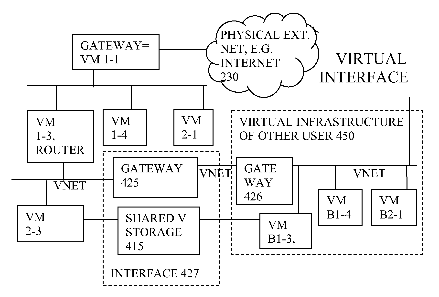
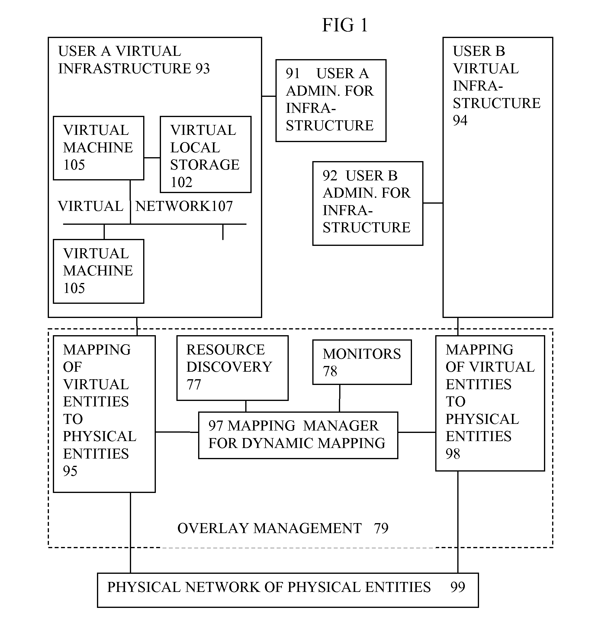
[0070]In the embodiments described, an existing IT infrastructure is dynamically partitioned into a set of virtual IT infrastructures: Overlay Infrastructures. These will be discussed first in general terms.

Overlay Infrastructures

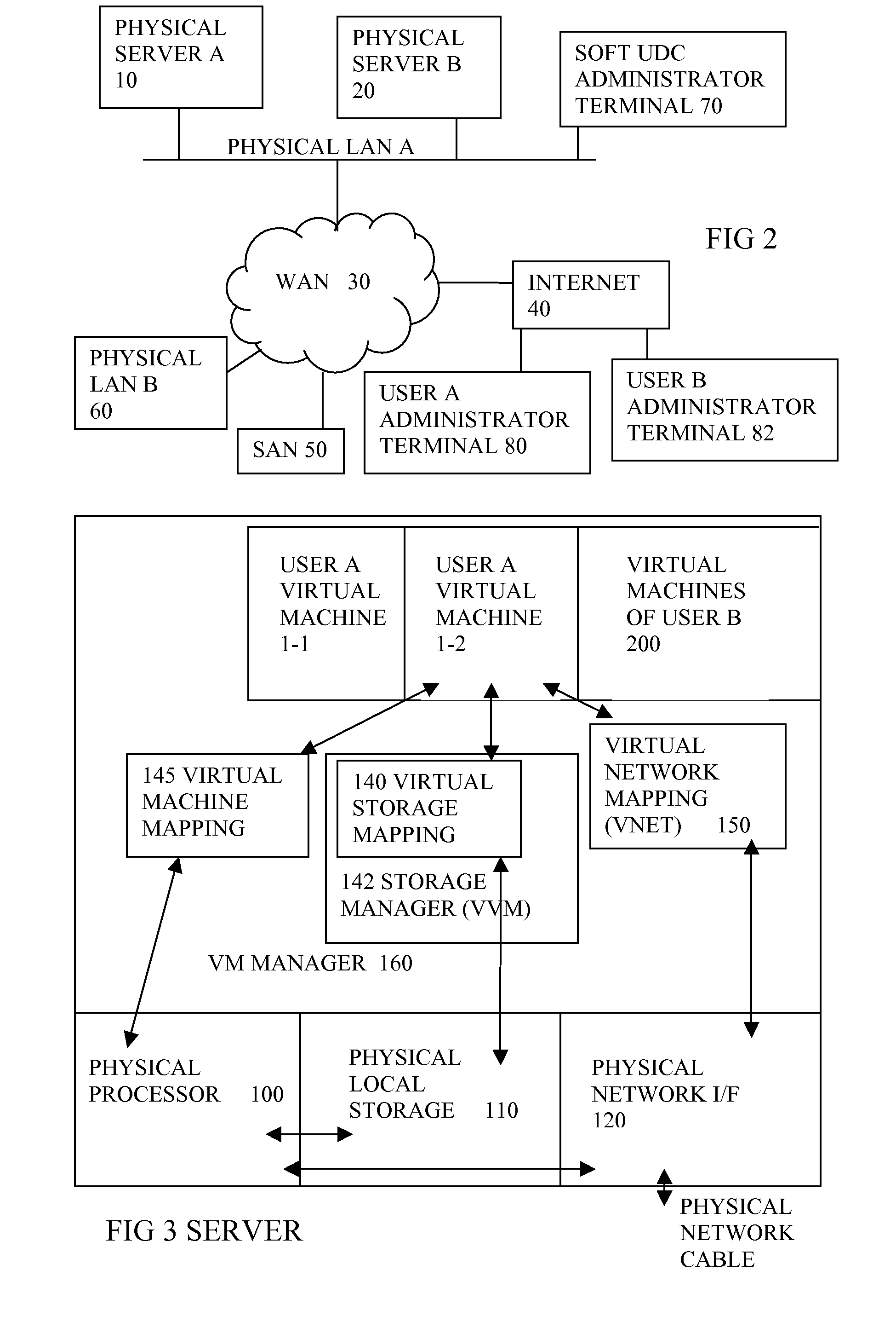
[0071]Many different overlay infrastructures may share the same physical hardware resources: network, computers and storage devices. Each overlay is configured independently of other overlays and independently of the underlying hardware configuration. The combined number of virtual resources in all the overlays can far exceed the total number of physical resources in the physical infrastructure. The assignment of physical resources to an overlay is varied dynamically to meet business needs.

[0072]An overlay infrastructure is a complete IT infrastructure. Within a overlay infrastructure instances of operating systems run applications. The overlay infrastructure is completely transparent to these operating systems and applications: it is if they were running o...


PUM


Abstract

A system has a virtual overlay infrastructure mapped onto physical resources for processing, storage and network communications, the virtual infrastructure having virtual entities for processing, storage and network communications. The system has a mapping manager to dynamically alter the mapping for balancing, performance, and redundancy. There can be more independence from the underlying physical configuration, compared to known methods of virtualizing only some of the entities. The mapping manager can be distributed across a number of entities on different physical servers arranged to cooperate with each other.

Description

[0001]The present application is a National Phase entry based on International Application Number PCT / EP2005 / 055640, filed Oct. 28, 2005, which in turn corresponds to GB Application Number 0424149.3 filed Oct. 29, 2004, the disclosure of each of which is hereby incorporated by reference herein in its entirety. This application relates to co-pending applications having International Application numbers PCT / EP2005 / 055642 (entitled “Virtual Computing Infrastructure”, Applicant Docket Number 200407525), International Application number PCT / EP2005 / 055639 (entitled “Virtual Computing Infrastructure”, Applicant Docket number 200407612) and International Application number PCT / EP2005 / 055638 (entitled “Virtual Computing Infrastructure”, Applicant Docket number 200407628) the US National Phase entries of each of which are filed on the same day as the present application and which are hereby incorporated by reference herein in their entirety.FIELD OF THE INVENTION[0002]The invention relates to...

Claims


Application Information

Patent Timeline
Patent Type & Authority Applications(United States)
IPC IPC(8): G06F9/455G06F9/50H04L29/08
CPCH04L67/1097G06F9/5077
Inventor EDWARDS, NIGELDALTON, CHRIS I.BALDWIN, ADRIAN JOHNGOLDSACK, PATRICKLAIN, ANTONIO
Owner HEWLETT PACKARD DEV CO LP
Why Eureka
Try Eureka