Boil off gas management during ship-to-ship transfer of LNG

a technology of boiloff gas and transfer process, which is applied in the direction of gas/liquid distribution and storage, auxiliaries, and propulsive elements, can solve the problems of large cost of building and operating such facilities, and the typical size of regasification facilities, and achieve the effect of reducing the pressure within the storage tank of the receiving vessel

Inactive Publication Date: 2009-08-13
WOODSIDE ENERGY
View PDF88 Cites 10 Cited by
  • Summary
  • Abstract
  • Description
  • Claims
  • Application Information

AI Technical Summary

Benefits of technology

[0020]a regasification facility onboard the self-propelled receiving vessel for reducing the pressure within the receiving vessel storage tank to a normal operating pressure during regasification of LNG to produce natural gas when the self-propelled receiving vessel transits from the ship-to-ship transfer location to a regasification location closer to shore.
[0024]To cope with the stresses which accompany intermediate fluid levels, it is preferably that the receiving storage tank either eliminates sloshing or is robust to sloshing of the LNG when the storage tank is partly filled. The receiving vessel storage tank may be a self-supporting or a prismatic or a membrane tank.
[0025]The receiving vessel may further include a recess disposed within the hull and towards the bow of the receiving vessel for receiving a submersible, disconnectable mooring buoy for mooring the receiving vessel at a regasification location. To reduce environmental impact, the onboard regasification facility preferably uses ambient air as a source of heat. In one form, the LNG is regasified through heat exchange with an intermediate fluid and the intermediate fluid is heated using ambient air as a source of heat to the onboard regasification facility. Heat exchange between the ambient air and the LNG or between ambient air and an intermediate fluid may be encouraged through use of forced draft fans.

Problems solved by technology

Such onshore storage and regasification facilities are typically large and the costs associated with building and operating such facilities are significant.

Method used


Image

  • Boil off gas management during ship-to-ship transfer of LNG
  • Boil off gas management during ship-to-ship transfer of LNG
  • Boil off gas management during ship-to-ship transfer of LNG

Examples


Embodiment Construction

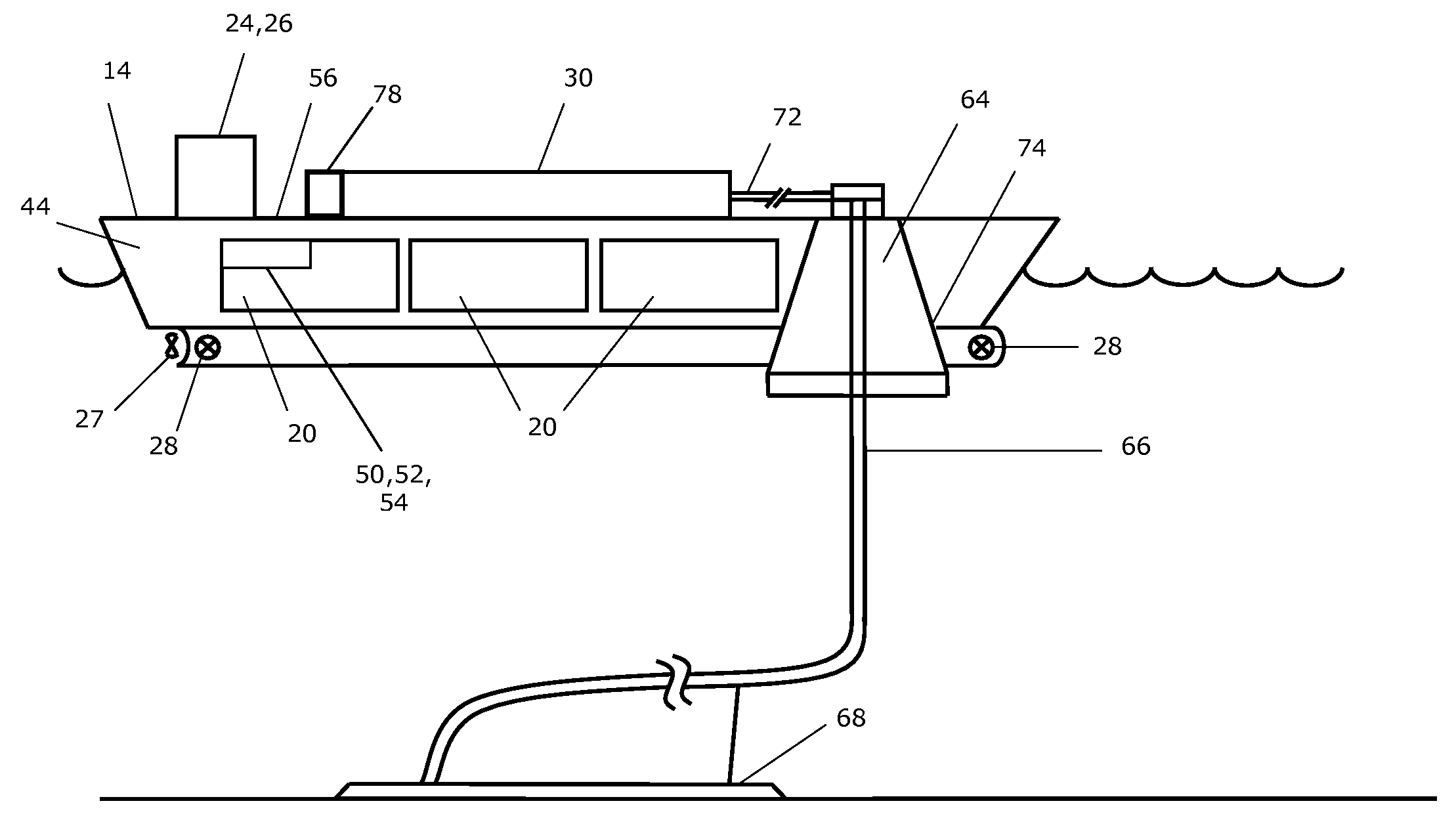
[0033]Particular embodiments of a process and system for ship-to-ship transfer of liquefied natural gas (LNG) from a delivery vessel to a receiving vessel at sea are now described. The terminology used herein is for the purpose of describing particular embodiments only, and is not intended to limit the scope of the present invention. Unless defined otherwise, all technical and scientific terms used herein have the same meanings as commonly understood by one of ordinary skill in the art to which this invention belongs.

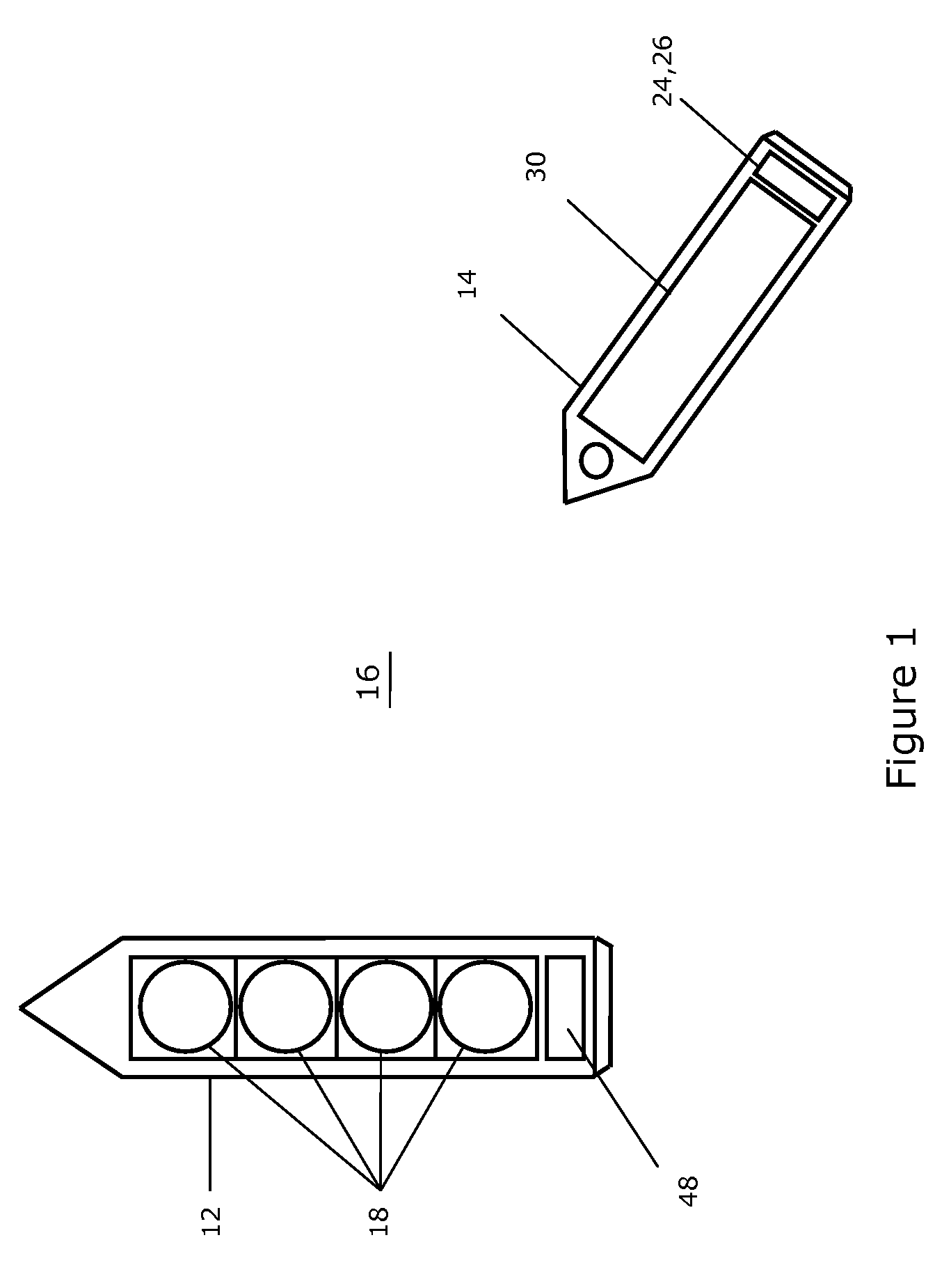
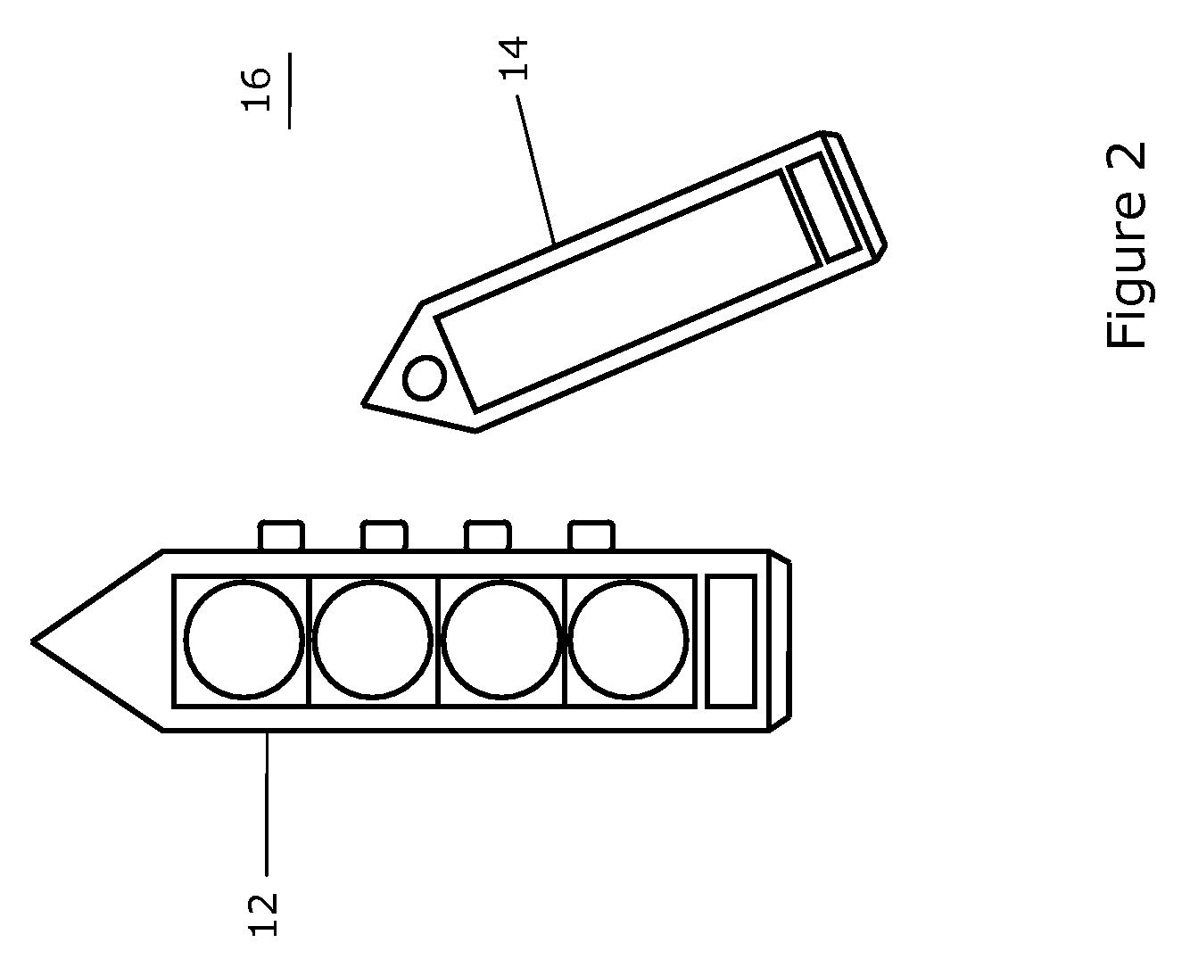
[0034]An embodiment of the present invention is now described with reference to FIGS. 1 to 5. In this embodiment, a delivery vessel 12 is loaded with a cargo of LNG at an export terminal (not shown). In this example, the delivery vessel 12 is a traditional LNG Carrier fitted with Moss-style cryogenic storage tanks. The loaded delivery vessel 12 then travels towards an import terminal located typically in a different country to the country of origin where the export term...


PUM


Abstract

The present invention relates to a process and system for managing boil-off gas generated during ship-to-ship transfer of LNG at sea. The LNG is transferred from a storage tank onboard a delivery vessel to a storage tank onboard a receiving vessel. The process includes the steps of a) operating the receiving vessel storage tank at a pressure greater than the operating pressure of the delivery vessel storage tank; and, b) transferring a portion of the boil-off gas from the receiving vessel storage tank to the delivery vessel storage tank onboard.

Description

CROSS REFERENCE TO RELATED APPLICATIONS[0001]This application is a continuation of PCT / AU2007 / 001316, filed Sep. 7, 2007, and titled “Boil Off Gas Management During Ship-To-Ship Transfer of LNG,” which claims priority to U.S. Provisional Patent Application Ser. No. 60 / 843,395, filed on Sep. 11, 2006, the entire contents of which are hereby incorporated by reference.FIELD OF THE INVENTION[0002]The present invention relates to a process and a system for managing boil-off gas generated during ship-to-ship transfer of LNG at sea, the LNG being transferred from a storage tank onboard a delivery vessel to a storage tank onboard a receiving vessel.BACKGROUND TO THE INVENTION[0003]Natural gas is the cleanest burning fossil fuel as it produces less emissions and pollutants than either coal or oil. Natural gas (“NG”) is routinely transported from one location to another location in its liquid state as “Liquefied Natural Gas (“LNG”). Liquefaction of the natural gas makes it more economical to ...

Claims


Application Information

Patent Timeline
Patent Type & Authority Applications(United States)
IPC IPC(8): F17C9/00F17C9/04B63J99/00
CPCB63B2770/00F17C5/02F17C2270/0102F17C2260/035F17C2265/032F17C2221/033B63H21/38Y02T70/50Y02T90/40B63J99/00F17C9/00
Inventor FAKA, SOLOMON ALADJA
Owner WOODSIDE ENERGY
Why Eureka
Try Eureka