Fin-tube heat exchanger, fin for heat exchanger, and heat pump apparatus

a heat exchanger and fin technology, applied in the direction of indirect heat exchangers, lighting and heating apparatuses, refrigeration machines, etc., to achieve the effects of improving heat transfer performance, increasing heat transfer area, and increasing flow velocity

Inactive Publication Date: 2009-08-13
PANASONIC CORP
View PDF1 Cites 40 Cited by
  • Summary
  • Abstract
  • Description
  • Claims
  • Application Information

AI Technical Summary

Benefits of technology

[0149]A fin 32 shown in the plan view of FIG. 21 suitably may be employed for the fin-tube heat exchanger 1. The arrangement and dimensions of the heat transfer tubes 2 are common to those in Embodiment 4. The difference is that second protrusions 53 are formed between the protrusions 35 formed in the front row and the other protrusions 35 formed in the rear row, the second protrusions 53 having a surface area smaller than the foregoing protrusions 35, 35. Strictly speaking, in FIG. 21, which is a plan view showing the fin 32 viewed in plan from the height direction (Y direction) perpendicular to the principal surface, the diameter d4 of the second protrusions 53 is smaller than the outer diameter D of the heat transfer tubes 2. In addition, the second protrusions 53 protrude in the same direction as the protrusions 35, 35 in the front row and the rear row.
[0150]In the fin 30 according to Embodiment 4 (see FIG. 14), there is a little space between the protrusions 35 in the front row and the protrusions 35 in the rear row. By forming the second protrusions 53 in this space, the heat transfer area increases. In particular, the region in which the second protrusions 53 are formed serves as a passage of the air A whose flow velocity has been increased by the effect of the protrusions 35 in the front row. Therefore, by allowing the air A with an increased flow velocity to hit the second protrusions 53 intentionally, it is possible to improve the heat transfer performance further. Such second protrusions 53 may have a circular hump shape as in the present embodiment, or they may have an elliptical hump shape.
[0151]In addition, a fin 33 as illustrated in FIG. 22 also can be employed suitably for the same reasons as described above. In the fin 33, protrusions 51, 51 in a circular hump shape are formed in the front row and the rear row in place of the protrusions 35 in an elliptical hump, and second protrusions 53 having a smalle...

Problems solved by technology

In recent years, demands for reducing energy consumption of heat pump apparatuses used for hot water heaters and air condition...

Method used


Image

  • Fin-tube heat exchanger, fin for heat exchanger, and heat pump apparatus
  • Fin-tube heat exchanger, fin for heat exchanger, and heat pump apparatus
  • Fin-tube heat exchanger, fin for heat exchanger, and heat pump apparatus

Examples


embodiment 1

[0079]Hereinbelow, one embodiment of the present invention is described with reference to the appended drawings.

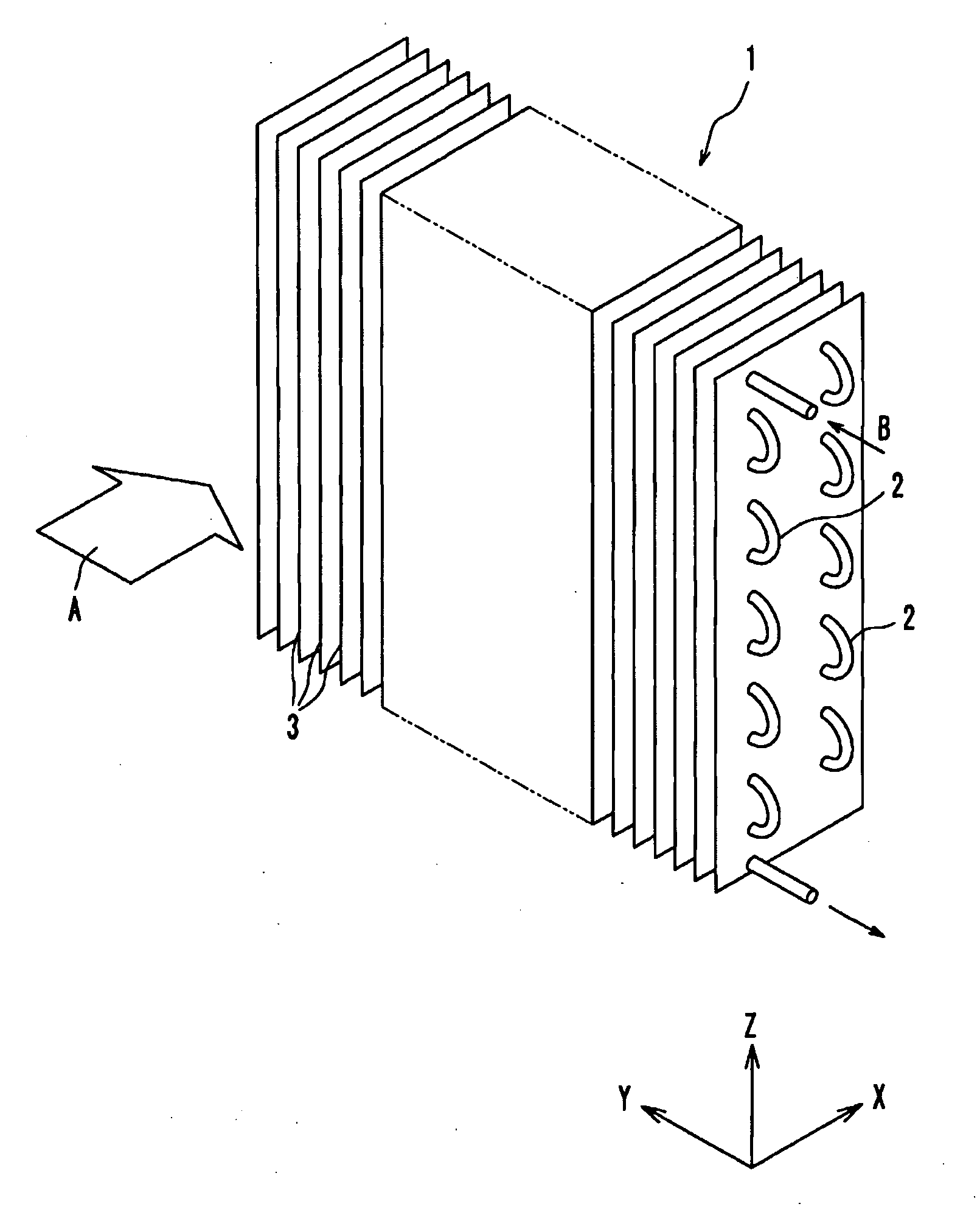
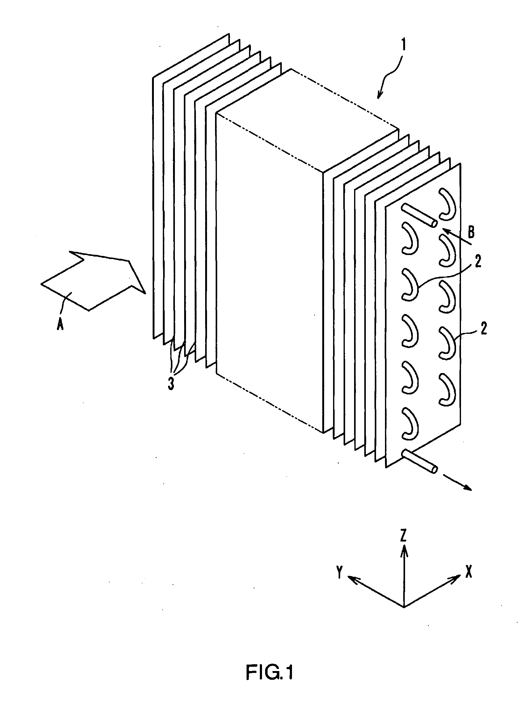
[0080]FIG. 1 is an overall perspective view illustrating a fin-tube heat exchanger according to the present embodiment. The fin-tube heat exchanger 1 has a plurality of fins 3 arranged parallel to each other with a predetermined gap for forming spaces for allowing the first fluid to flow therethrough, and a plurality of heat transfer tubes 2 penetrating these fins 3. The heat exchanger 1 is for exchanging heat between the first fluid flowing along the principal surfaces of the fins 3 and the second fluid flowing inside the heat transfer tubes 2. In the present embodiment, air A flows along the principal surfaces of the fins 3, and refrigerant B flows inside the heat transfer tubes 2. The plurality of heat transfer tubes 2 penetrating the fins 3 are connected in a single line so that the refrigerant B flows therein in turn. It should be noted that the type and state of the ...

embodiment 2

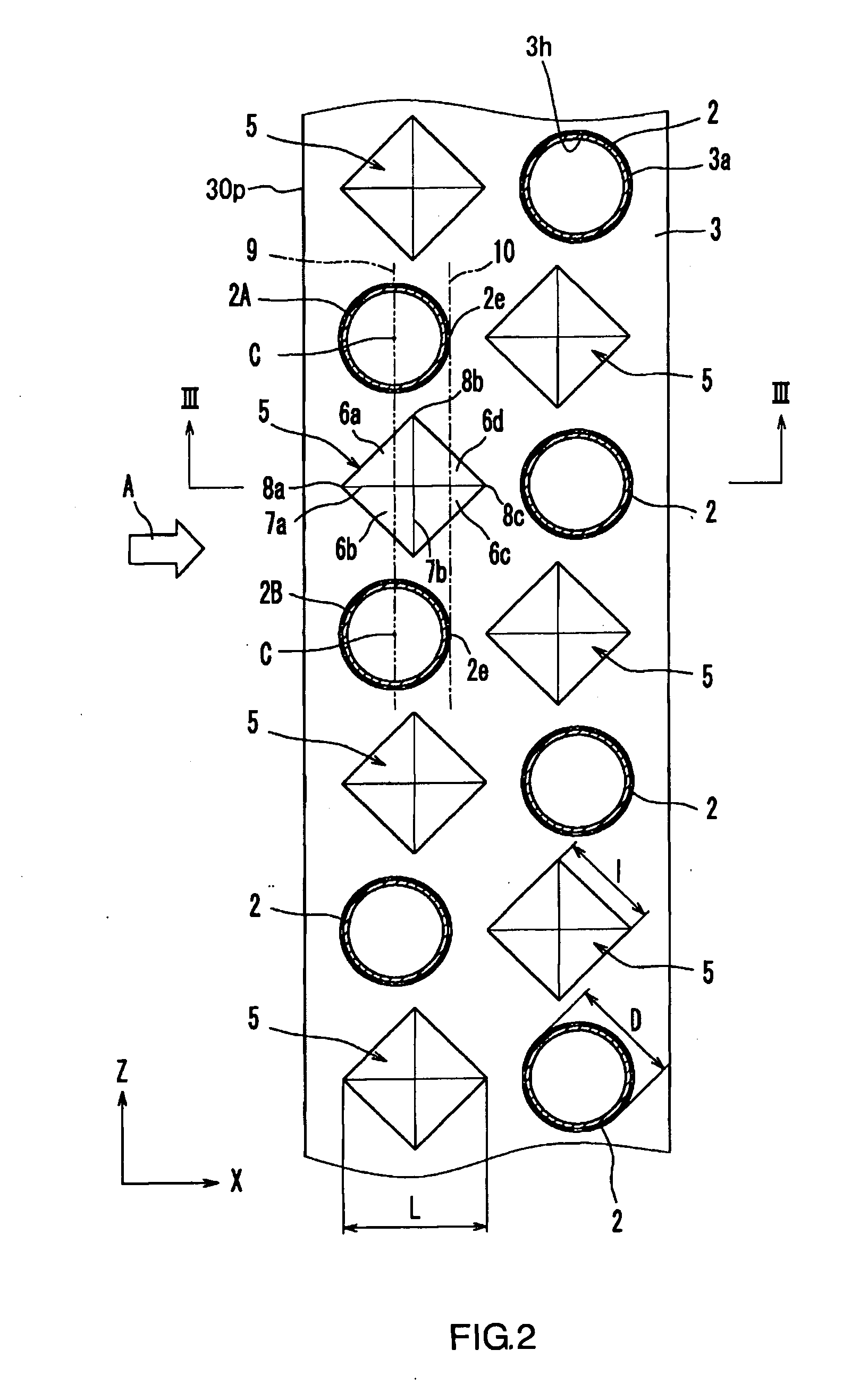
[0110]As illustrated in FIGS. 10 and 11, a fin 13 according to the present embodiment has protrusions 15 formed in a circular conic shape. In the present embodiment, the protrusion 15 has no clear ridge line. However, assuming a virtual line 7a extending from an upstream edge 8a to an apex 11 in the X direction and a virtual line 7b extending through the apex 11 in the Z direction, it is understood that a first slanted surface 6a, which guides the air toward the first heat transfer tube 2A side, and a second slanted surface 6b, which guides the air toward the second heat transfer tube 2B side, are formed between the virtual line 7a and the virtual line 7b.

[0111]In the present embodiment as well, the width of each of the protrusions 15 increases from the upstream edge 8a to the intermediate portion 8b, while it decreases from the intermediate portion 8b to the downstream edge 8c. The upstream edges 8a of the protrusions 15 are located upstream of the centers C of the heat transfer t...

embodiment 3

[0115]As illustrated in FIG. 12, a fin 23 according to Embodiment 3 has protrusions 25 that are formed in an elliptic conic shape. Herein, the ellipticity (the ratio of the major axis to the minor axis) is set at about 2. However, the ellipticity of the protrusions 25 is not particularly limited. The ellipticity may be greater than 1 but equal to or less than 2, or it may be equal to or greater than 0.5 but less than 1. The protrusions 25 may have an elliptic conic shape that is slender in the X direction or an elliptic conic shape that is slender in the Z direction.

[0116]In the present embodiment as well, the protrusion 25 has no clear ridge line. However, as in the case of Embodiment 2, assuming a virtual line 7a extending from an upstream edge 8a to an apex 11 in the X direction and a virtual line 7b extending through the apex 11 in the Z direction, it is understood that a first slanted surface 6a, which guides the air toward the first heat transfer tube 2A side, and a second sla...


PUM


Abstract

A fin-tube heat exchanger 1 includes a plurality of fins 3 arrayed spaced apart from and parallel to each other so as to form gaps for allowing a first fluid to flow therethrough, and a plurality of heat transfer tubes 2 penetrating the plurality of fins 3 and for allowing a second fluid to flow therethrough. The plurality of heat transfer tubes 2 includes first heat transfer tubes 2A and second heat transfer tubes 2B arranged in a predetermined row direction that intersects the flow direction of the first fluid. The fins 3 have protrusions 5 each disposed between a first heat transfer tube 2A and a second heat transfer tube 2B, for guiding the first fluid toward the first heat transfer tube 2A side and the second heat transfer tube 2B side. The equivalent diameter of the protrusion 5, as viewed in the axis direction of the heat transfer tubes 2, is equal to or greater than the outer diameter of the heat transfer tubes 2.

Description

TECHNICAL FIELD[0001]The present invention relates to fin-tube heat exchangers, fins for heat exchangers, and heat pump apparatuses.BACKGROUND ART[0002]Conventionally, fin-tube heat exchangers have been used for various apparatuses such as air conditioners, freezer-refrigerators, dehumidifiers, and hot water heaters. A fin-tube heat exchanger is composed of a plurality of fins that are arranged parallel to each other and spaced apart with a predetermined gap, and heat transfer tubes that extend through these fins.[0003]Known fin-tube heat exchangers include ones with various fin shape designs so as to, for example, enhance heat transfer and reduce pressure loss. For example, in a fin-tube heat exchanger, the leeward side of the heat transfer tube usually becomes a dead fluid zone, in which the heat transfer coefficient is locally low. In view of this, there are known fin-tube heat exchangers having fins provided with protuberances on the surfaces of the fins so as to reduce the dead...

Claims


Application Information

Patent Timeline
IPC IPC(8): F25B13/00F28D7/00F28F1/24
CPCF28D1/0477F28F1/325F28F1/32
Inventor OGAWA, OSAMUKOMORI, KOU
Owner PANASONIC CORP
Why Eureka
Try Eureka