Driving Device

Active Publication Date: 2009-08-13
STABILUS
View PDF3 Cites 24 Cited by
  • Summary
  • Abstract
  • Description
  • Claims
  • Application Information

AI Technical Summary

Benefits of technology

[0005]It is an object of the invention to provide a driving device of

Problems solved by technology

This construction requires a large installat

Method used


Image

  • Driving Device
  • Driving Device
  • Driving Device

Examples


Embodiment Construction

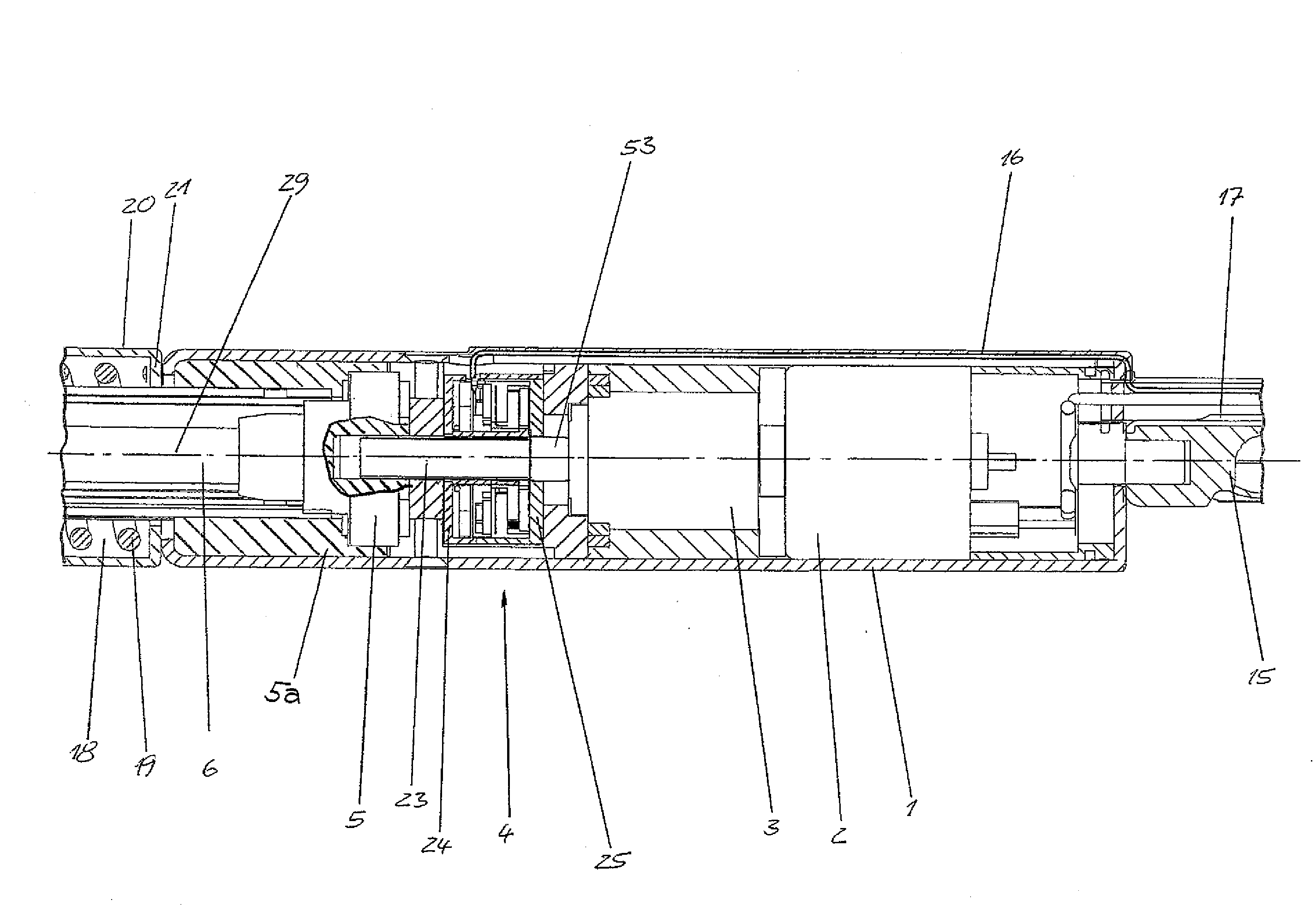
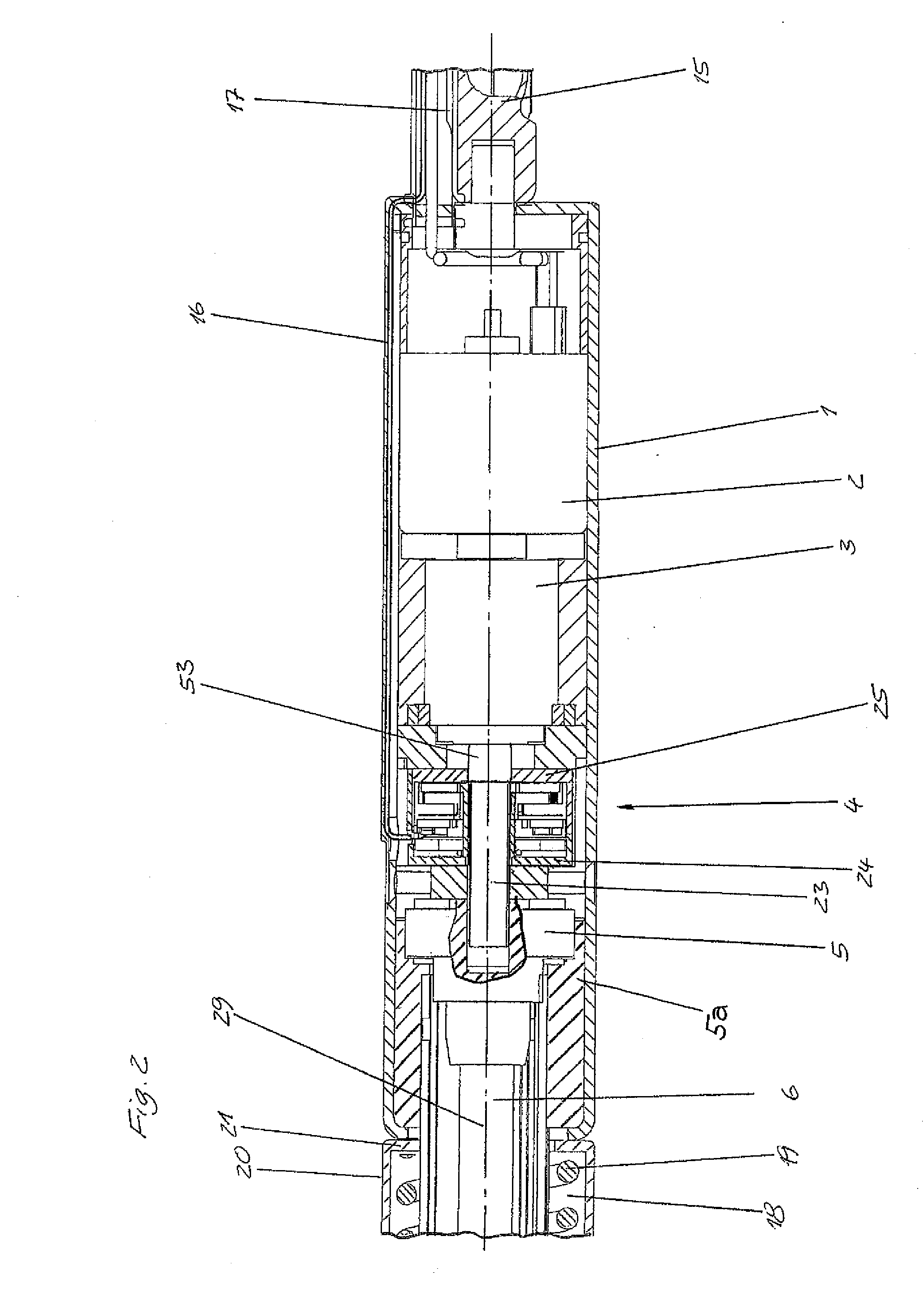
[0060]The driving device shown in the drawings has a housing tube 1 in which an electric motor 2, a gear unit 3 which can be driven by the electric motor 2, and a sensor assembly 4 are arranged in series one after the other.

[0061]It is also possible to arrange a clutch in the drivetrain, in which case the sensor assembly 4 preferably follows the clutch so that a manual movement of the hatch can also be sensed.

[0062]Following the sensor assembly 4 in sequence is a spindle adapter 5 which is supported at a bearing 5a and connected coaxially to a rotatably mounted threaded spindle 6.

[0063]A spindle nut 7 is arranged on the threaded spindle 6 so as to be axially displaceable in a guide tube 8 which is fixedly connected coaxially to the housing tube 1.

[0064]The spindle nut 7 engages in axial slots 10 at the inner wall of the guide tube 8 by supporting pins 9 which project out radially so that the spindle nut 7 is fixed against rotation relative to the guide tube 8.

[0065]The threaded spin...


PUM


Abstract

A driving device for a hatch in a motor vehicle includes a first fastening element which can be connected to a stationary structural component, a second fastening element which can be connected to a movable structural component, a spindle drive including a threaded spindle having an axis of rotation and a spindle nut arranged on the threaded spindle, and a rotary drive having a driveshaft for rotating spindle to move the first fastening element axially relative to the second fastening element. A stroke detection sensor for continuously detecting the position of the movable structural component includes a rotatable sensor element driven in rotation by the driveshaft and a stationary sensor element for continuously detecting the rotational position of the rotatable sensor element. A gear reduction unit is provided between the driveshaft and the rotatable sensor element so the revolutions of the sensor element are reduced by about 14:1.

Description

BACKGROUND OF THE INVENTION[0001]1. Field of the Invention[0002]The invention relates to a driving device, particularly for a hatch in a motor vehicle, having a first fastening element which can be connected to a stationary structural component, a second fastening element which can be connected to a movable structural component, a spindle drive including a threaded spindle with a spindle nut arranged thereon, a rotary drive with a driveshaft for rotating the spindle to move the first fastening element axially relative to the second fastening element, a stroke detection sensor for detecting the position of the movable structural component, and a spindle sensor for detecting the revolutions of the spindle.[0003]2. Description of the Related Art[0004]In a driving device of the type mentioned above, it is known to detect the stroke position by means of a linear potentiometer and to detect the spindle revolutions by means of a Hall sensor. This construction requires a large installation ...

Claims


Application Information

Patent Timeline
IPC IPC(8): F16H25/24F16H1/32F16H57/02G01R27/08H01L43/06
CPCE05Y2201/726E05Y2400/334E05Y2900/546Y10T74/2186E05F15/622Y10T74/19702F16H25/2015E05Y2400/41
Inventor BATOSKY, OLEGFRIEB-PREIS, TIMOHILLEN, JORGKOHNS, PETER
Owner STABILUS
Why Eureka
Try Eureka