Flue baffle for gas-fired hot water tanks

a technology for hot water tanks and flue pipes, which is applied in the direction of steam generation, furnace-tube steam boilers, steam boilers, etc., can solve the problems of reducing affecting the efficiency of hot water heaters, etc., and achieves low labor costs and low fabrication costs.

Inactive Publication Date: 2009-08-13
LESAGE CLAUDE
View PDF16 Cites 8 Cited by
  • Summary
  • Abstract
  • Description
  • Claims
  • Application Information

AI Technical Summary

Benefits of technology

[0006]Another feature of the present invention is to provide a flue baffle which can be automatically constructed at low labour cost and/or low fabrication costs.
[0007]Another feature of the present invention is to provide a flue baffle which is entirely constructed from an elongated rectangular metal strip which is die-cut or laser-cut and then formed in forming dies without the need to assemble and weld parts.
[0008]According to the above features, from a broad aspect, the present invention provides a flue baffle for use. in a hot water tank flue pipe wherein the flue pipe is adapted to be in contact with wa...

Problems solved by technology

One problem with existing flue baffles that are suspended, such as the flue baffle described in my U.S. Pat. No. 5,544,625 is that during transport of these hot water heaters the transport container containing the hot water heater can be laid down on its side in a transport vehicle, although this is not recommended.
Also, the container can be mishandled.
This often causes the flue baffle to be displaced within the flue pipe or be damaged.
The result is that an improperly aligned or damaged baffle reduces the efficiency of the hot water heater as the flue baffle no longer provides the performance that it was designed to deliver when properly installed.
Because these flue baffles are not inspected at the time of installation ...

Method used


Image

  • Flue baffle for gas-fired hot water tanks
  • Flue baffle for gas-fired hot water tanks
  • Flue baffle for gas-fired hot water tanks

Examples


Embodiment Construction

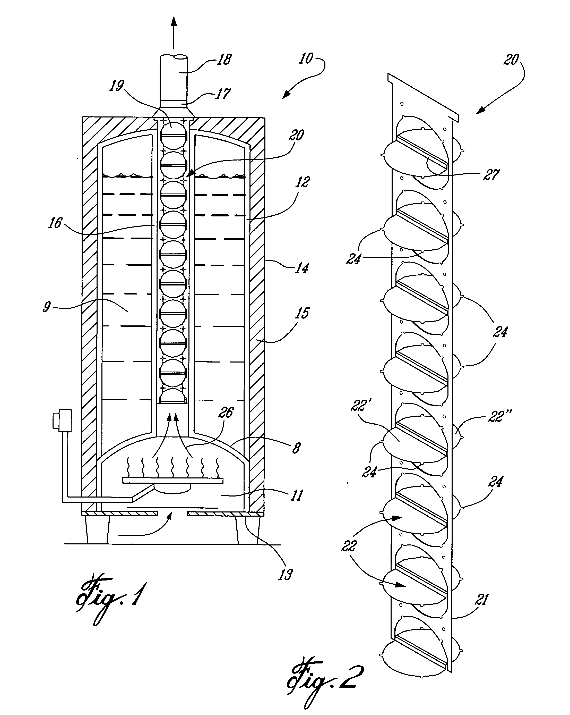
[0016]Referring now to the drawings and more particularly to FIG. 1, there is shown generally at 10 a hot water heater of the type provided with a gas or oil burner chamber 11 at a lower end of an inner tank housing 12. The inner tank housing 12 is supported on a base 13 and concealed within an outer thin metal casing 14. Insulating material 15 is disposed between the inner casing 12 and the outer casing 14.

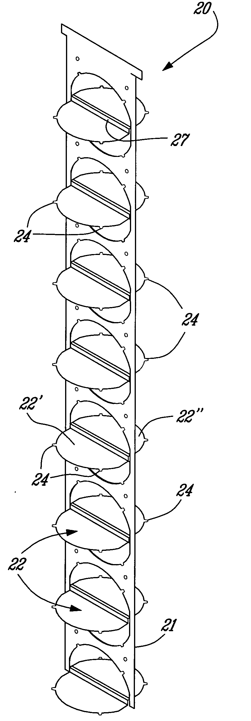
[0017]As hereinshown a flue pipe 16 extends centrally within the inner tank housing 12 and exits the hot water heater through a coupling 17 at a top end to couple the flue pipe 16 to an exhaust duct 18. Although not shown, a fan is usually connected to the exhaust duct to draw the combustion gases through the flue pipe 16 to exhaust the combustion gases to atmosphere. As hereinshown, the flue baffle 20 of the present invention is suspended into the flue pipe 16.

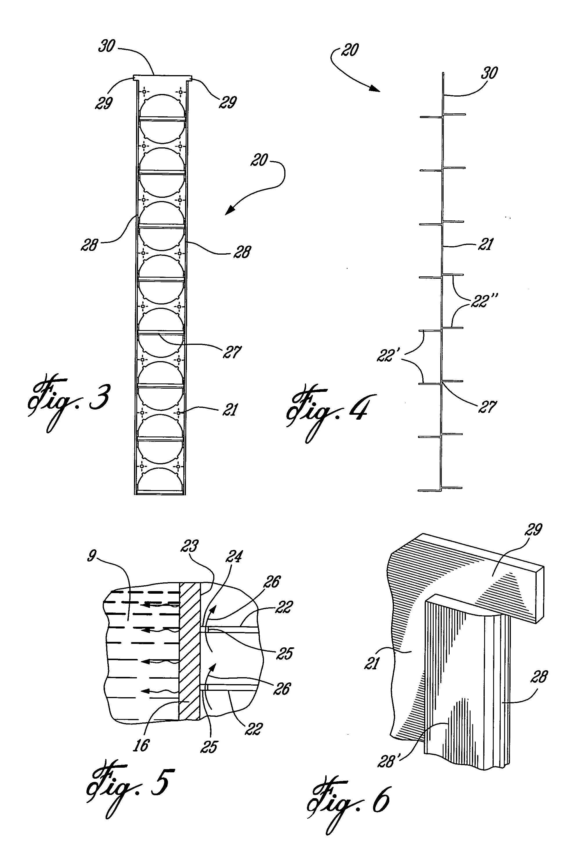
[0018]Referring now to FIGS. 2 to 6, there will be described the construction and operation of the flue baffle 20 of the...


PUM


Abstract

A flue baffle for use in a hot water tank flue pipe which is disposed to be in contact with water contained in an inner tank of the hot water heater. A burner chamber is provided at a lower end of the inner tank. The flue baffle is comprised of an elongated rectangular metal strip which has a plurality of spaced circular metal discs disposed substantially transverse to the strip and to the longitudinal axis of the flue pipe. The metal discs are dimensioned to be spaced from an inner surface of the flue pipe. Two or more spacing nipples protrude from a circumferential outer edge of the circular metal discs and are spaced apart from one another for slight frictional engagement with the inner surface of the flue pipe to maintain a substantially constant circumferential passage between the circumferential outer edge of the discs and the inner surface of the flue pipe.

Description

TECHNICAL FIELD[0001]The present invention relates to a flue baffle for use in a hot water tank flue pipe through which flue gases from a burner chamber at the base thereof are discharged. The flue baffle creates turbulence and resistance of the flue gases to enhance heat exchange between the hot gases and the flue pipe and between the flue pipe and the water being heated in an inner tank and which is in direct contact with the exterior surface of the flue pipe.BACKGROUND ART[0002]It is known to mount a flue baffle inside a flue pipe of gas- or oil-fired water heater to retard the flow of exhausted hot gas from the lower burner chamber. As the gases escape upwards in the flue pipe they are retarded due to the resistance offered by the flue baffle to enhance heat exchange to transfer heat from the flue gases to the water surrounding a major portion of the flue pipe. At the same time, the flue gases are cooled as they rise up the flue pipe. The more efficient the flue baffle design is...

Claims


Application Information

Patent Timeline
IPC IPC(8): F22B7/12
CPCF22B13/005F22B37/06F22B13/14F22B13/02
Inventor LESAGE, CLAUDE
Owner LESAGE CLAUDE
Why Eureka
Try Eureka