On/Off-Road Tire For A Motor Vehicle
a technology for motor vehicles and tires, applied in off-road vehicle tires, vehicle components, non-skid devices, etc., can solve the problems of tire manufacturers, difficult to achieve, and the performance of pneumatic tires mounted on all-terrain motor vehicles, so as to improve wear resistance, reduce noise, and improve on-road performance
- Summary
- Abstract
- Description
- Claims
- Application Information
AI Technical Summary
Benefits of technology
Problems solved by technology
Method used
Image

Examples
first embodiment
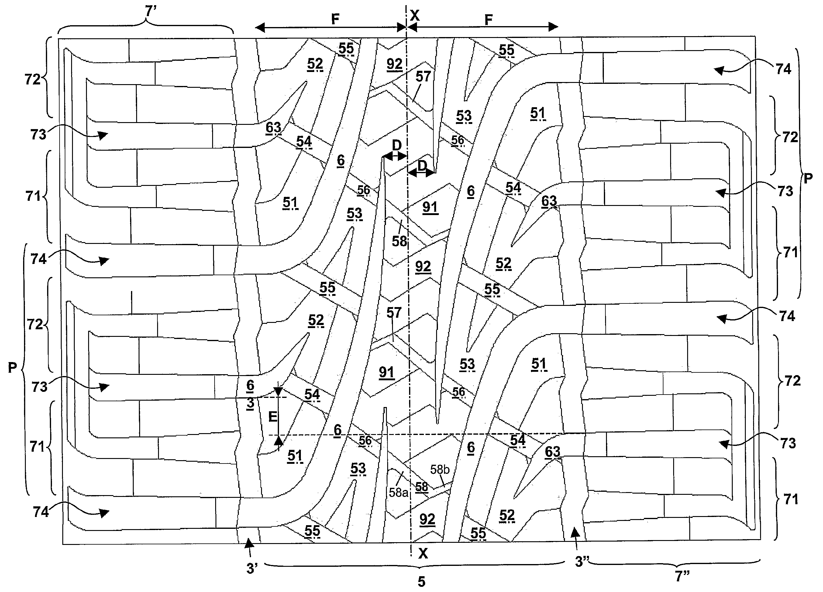
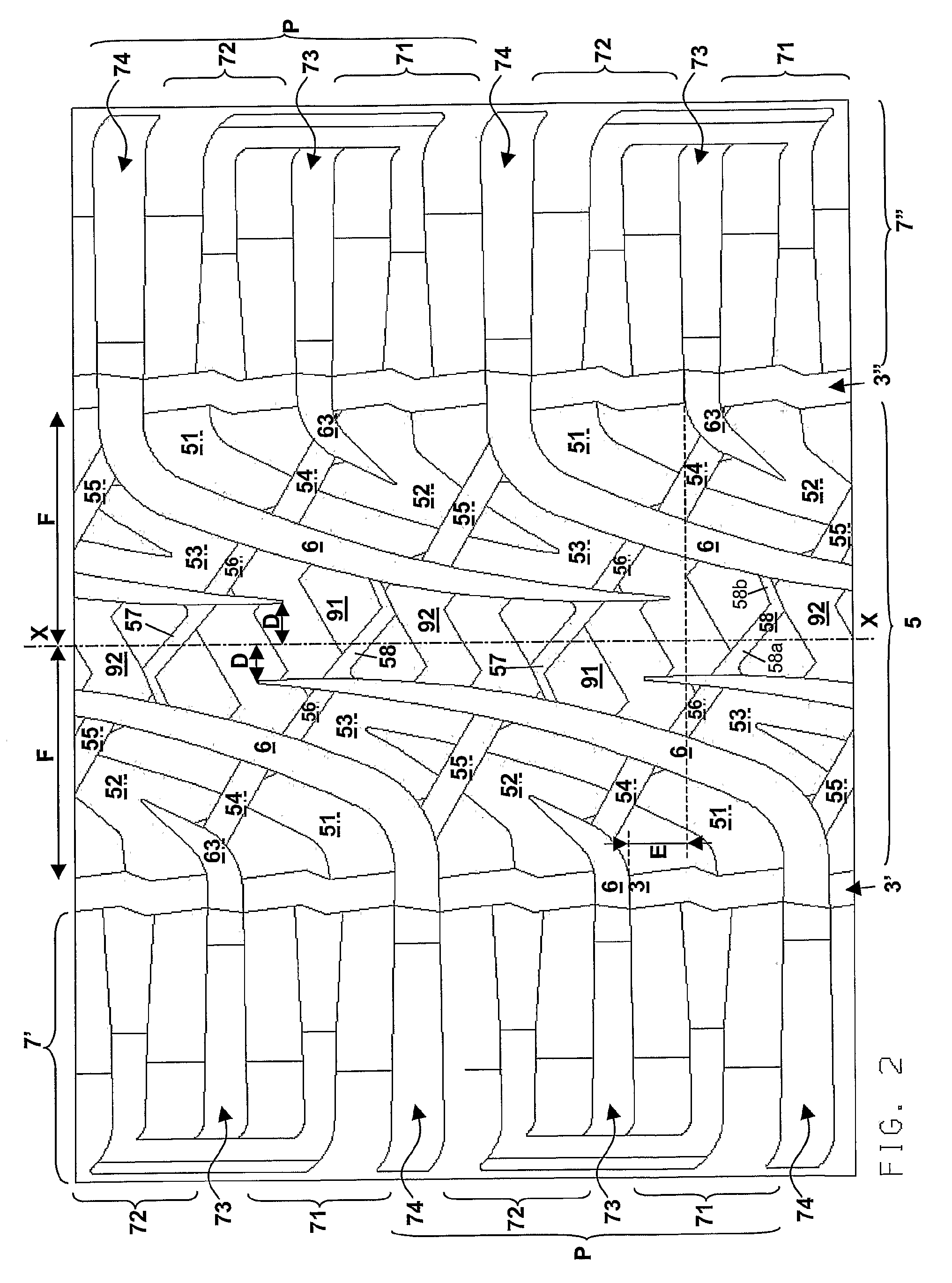
[0045]Hereinbelow, a detailed description of tread 2 of the tire according to the present invention is given by starting from the left side thereof and with reference to FIG. 2a which represents the left side portion of the tread 2 of FIG. 2.
[0046]Shoulder region 7′ comprises a plurality of circumferentially consecutive shoulder blocks 71, 72. Shoulder blocks 71, 72 are separated from each other by shoulder transverse grooves 73, 74. Preferably, shoulder transverse grooves 73, 74 are circumferentially alternated between circumferentially consecutive shoulder blocks 71, 72. Preferably, shoulder transverse grooves 73, 74 are substantially parallel to a radial plane of the tire. According to FIGS. 2 and 2a, shoulder blocks 71, 72 have a substantially rectangular shape.
[0047]Axially inner (i.e. closer to the tire equatorial plane) longitudinal sides 71a, 72a of shoulder blocks 71, 72, respectively, face the circumferential groove 3′. In other words, the succession in the circumferential...
second embodiment
[0116]First central transverse groove 54 shown in FIGS. 3 and 3a is elbow shaped. This means that first central transverse groove 54 comprises a first portion 54a and a second portion 54b which intersect to form the elbow shape. First portion 54a is inclined of an angle α. The first and second portions 54a, 54b form an angle φ ranging from about 120° to about 150°, preferably φ is about 135°. Preferably, first portion 54a is wider than second portion 54b. Preferably, the width of first portion 54a is comprised from about 5.0 mm to about 10.0 mm. Preferably, the depth of first portion 54a is comprised from about 8.0 mm to about 15.0 mm. Preferably, the width of second portion 54b is comprised from about 2.0 mm to about 6.0 mm. Preferably, the depth of second portion 54b is comprised from about 8.0 mm to about 15.0 mm.
[0117]Similarly to first central transverse groove 54, second central transverse groove 55 according to the second embodiment of the tread pattern of the present invent...
third embodiment
[0122]FIGS. 4 and 4a show tread pattern 2 according to the present invention said embodiment being similar to the first embodiment shown in FIGS. 2 and 2a. In fact, the only difference between the two embodiments lies in the shape of the shoulder blocks. Therefore, only a detailed description thereof will be given hereinbelow.
[0123]First shoulder block 71 comprises portions 71e, 71d and 71g. In FIG. 4a reference number 71f denotes a first transverse groove which is positioned between two circumferentially consecutive block projections 71′g. Preferably, first transverse groove 71f is a nail-shaped groove.
[0124]According to the embodiment shown in FIGS. 4 and 4a, in correspondence of the outermost (with respect to the tire equatorial plane) ends of the shoulder region 7′, shoulder transverse grooves 73, 74 are provided with a blind extended portion 76 which is inclined in a substantially circumferential direction. Extended portions 76 confer to shoulder transverse grooves 73, 74 a L s...
PUM
 Abstract
Description
Claims
Application Information
 - R&D
- Intellectual Property
- Life Sciences
- Materials
- Tech Scout
- Unparalleled Data Quality
- Higher Quality Content
- 60% Fewer Hallucinations
Browse by: Latest US Patents, China's latest patents, Technical Efficacy Thesaurus, Application Domain, Technology Topic, Popular Technical Reports.
© 2025 PatSnap. All rights reserved.Legal|Privacy policy|Modern Slavery Act Transparency Statement|Sitemap|About US| Contact US: help@patsnap.com