
Drive unit for motor vehicles with hybrid drive in a longitudinal arrangement

a technology of drive unit and hybrid drive, which is applied in the direction of electric energy vehicles, propulsion by batteries/cells, and engine-driven generators. it can solve the problems of extensive altering the entire vehicle, and it is not possible to solve the problem

Inactive Publication Date: 2009-08-13
MAGNA STEYR FAHRZEUGTECHN
View PDF7 Cites 24 Cited by
  • Summary
  • Abstract
  • Description
  • Claims
  • Application Information

AI Technical Summary

Benefits of technology

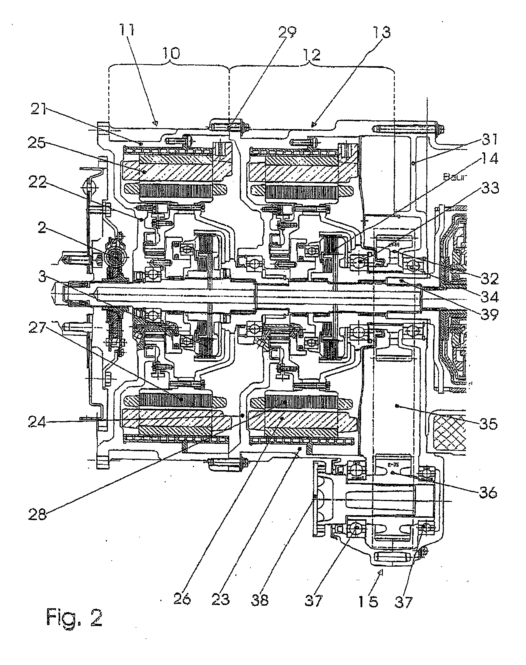
[0005]It is advantageous if the clutch is arranged within the electrical machine, since the electrical machines can thus be designed to have a rotation speed which is appropriate for the engine rotation speed and, owing to the larger radius of the rotor, can be designed to be very narrow.
[0006]In one development of the invention, the first electrical machine and the second electrical machine are each accommodated by a housing comprising a cylindrical casing and an axially normal wall, and the cylindrical casings are screwed to one another. The preconditions for a modular use are therefore provided, and the assembly of the two coaxial modules is simplified and the installation length further shortened.
[0007]If the electrical machine comprises a stator fixed in the housing and a rotor, and if the clutch in each case is a multi-plate clutch comprising an inner part and an outer part, in a further continuation of the concept of the invention, both the first and the second rotor are mounted in a bearing on the axially normal wall of the housing and have a replaceable coupling disk, which is connected to the clutch outer part such that it is fixed against rotation, the clutch being arranged between the bearing and the coupling disk. The replaceable coupling disk makes it possible to use identical rotors for both electrical machines; they are matched to their installation situation by fitting the respectively suitable coupling disk.
[0009]Advantageous developments consist in the fact that an actuator cylinder, which contains an annular piston, for the clutch is fixed to the axially normal wall, and the annular piston interacts with a contact-pressure plate of the clutch via a thrust bearing and that the first and / or the second electrical machine each have a rotation speed sensor, which is fixed to the axially normal wall, and a rotation speed transmitter collar is fitted to the rotor. The former makes it possible to actuate the clutches without a rotary input to a rotating part, and the latter makes control possible in which the meshing of a clutch is dependent on the rotation speed ratios.

Problems solved by technology

This has the disadvantage that if only one of the two drives is working, the other needs to be blocked in order to provide a supporting torque.
If, in the case of a drive train with a longitudinal design, the second driven axle is intended to be the front axle, it is not possible to solve this problem of space and it is also necessary to extensively alter the entire vehicle.

Method used


Image

  • Drive unit for motor vehicles with hybrid drive in a longitudinal arrangement
  • Drive unit for motor vehicles with hybrid drive in a longitudinal arrangement
  • Drive unit for motor vehicles with hybrid drive in a longitudinal arrangement

Examples


Embodiment Construction

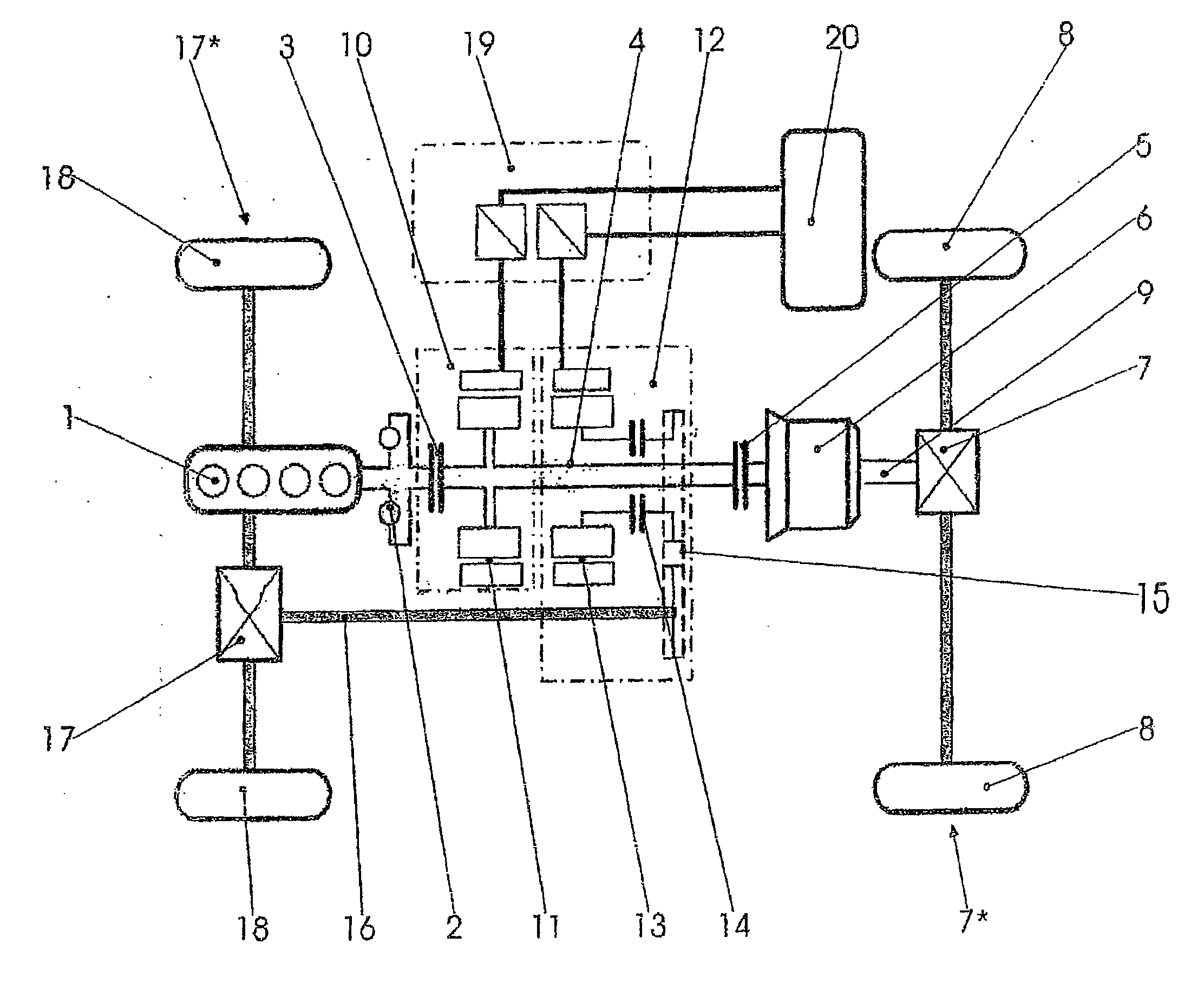
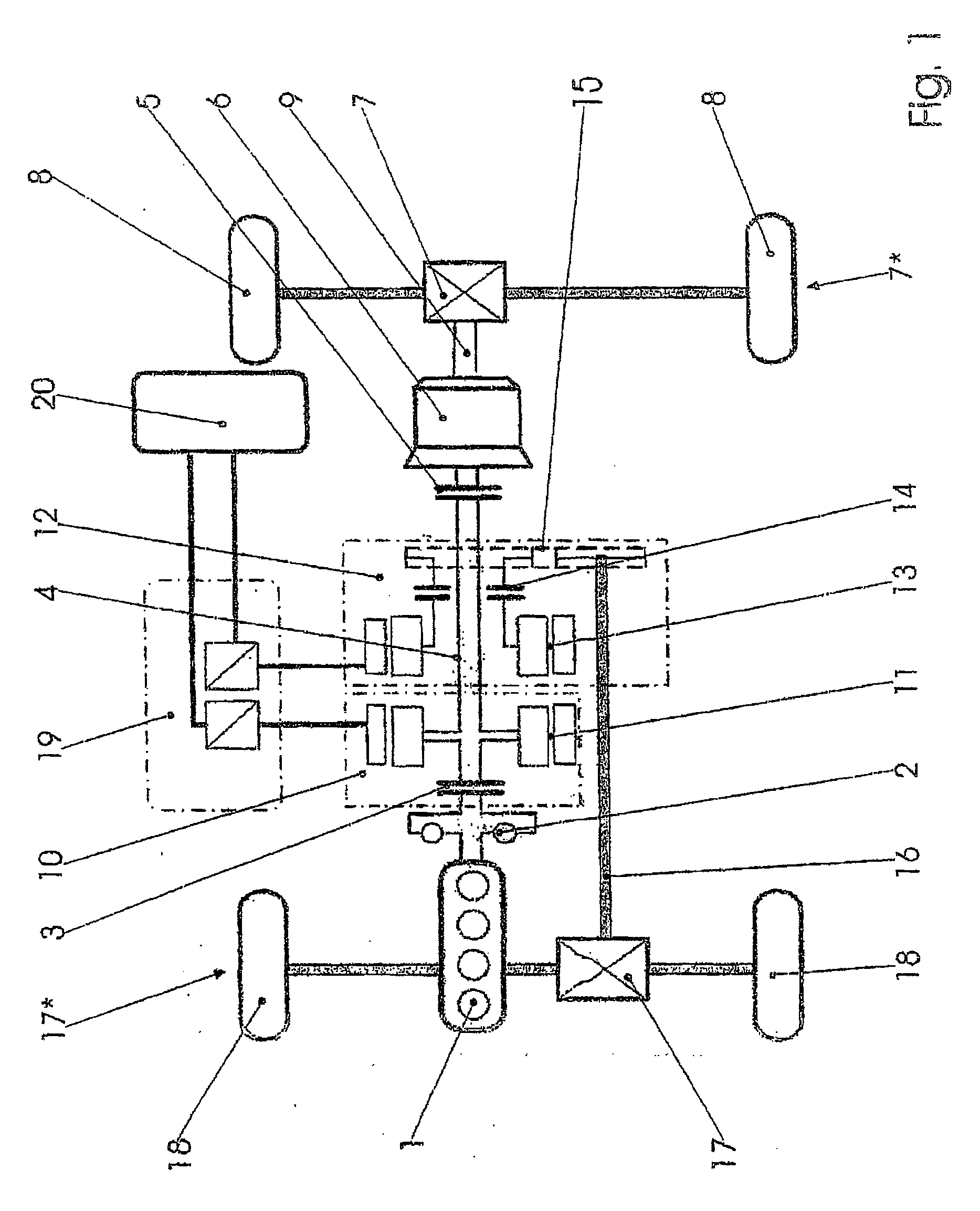
[0014]In FIG. 1, the internal combustion engine of a motor vehicle is denoted by 1. It is connected to a through-drive shaft 4 via an oscillation damper 2, possibly on a flywheel, and a first clutch 3. This through-drive shaft 4 drives a first driven axle 7*, in this case its axle gear mechanism 7 and therefore, in the exemplary embodiment shown, the rear wheels 8, via a second clutch 5 and a shift transmission 6.

[0015]The drive unit according to the invention comprises a first module 10 and a second module 12 directly adjacent thereto. A first electrical machine 11 is located in the first module 10, and a second electrical machine 13 is located in the second module 12. The second electrical machine 13 drives a propeller shaft 16 via a third clutch 14 and an offset drive 15, which propeller shaft 16 leads to the second driven axle 17*, and therefore to the front wheels 18 via an axle gear mechanism 17. In order to control the two electrical machines 11, 13, power electronics 19 are ...


PUM


Abstract

A drive unit for motor vehicles with hybrid drive and a drive train in a longitudinal arrangement, between the internal combustion engine and the first axle, comprising a housing piece, a through driveshaft, an electric motor, surrounding the through driveshaft with a first clutch before the electric motor and a second clutch thereafter, whereby a second axle is also to be driven with minimal space requirement. A first electric motor is thus physically combined with the first clutch, surrounding a second electric motor and the through driveshaft and is connected to the second axle by means of a third clutch, an offset gear and a shaft.

Description

BACKGROUND OF THE INVENTION[0001]The invention relates to a drive unit for a motor vehicle with a hybrid drive and a drive train in a longitudinal arrangement, which drive train also comprises an internal combustion engine, a longitudinal shaft for driving a first axle, and a gear mechanism, and which drive unit is arranged between the internal combustion engine and the first axle and comprises a housing part, a through-drive shaft, an electrical machine surrounding the through-drive shaft and a first clutch upstream of and a second clutch downstream of the electrical machine. With the longitudinal arrangement, the permanently driven, in this case the first, axle is generally the rear axle.[0002]Such a drive train is known from DE 29 43 554 C2, but is only illustrated schematically. The rotation speed ratios and structural features are now shown. In any case the electrical machine is used both as a drive or an additional drive and as a starter and generator. A few more details, if o...

Claims


Application Information

Patent Timeline
Patent Type & Authority Applications(United States)
IPC IPC(8): B60K6/40B60K6/387B60K6/405B60K6/48B60L50/16
CPCB60K1/02B60K6/387Y02T10/6221B60K6/48B60K6/405B60L15/2054B60L2240/507Y10S903/909Y10S903/91Y10S903/916Y10S903/912Y10S903/911Y02T10/72B60L50/61B60L50/16Y02T10/62Y02T10/64Y02T10/7072Y02T10/70
Inventor ZOHRER, FRANZERJAWETZ, KONSTANTINPICHLER, PETER
Owner MAGNA STEYR FAHRZEUGTECHN
Learn More