
Cleaning, pickling and electroplating apparatus

Inactive Publication Date: 2009-08-13
ALTMAN SHMUEL
View PDF14 Cites 2 Cited by
  • Summary
  • Abstract
  • Description
  • Claims
  • Application Information

AI Technical Summary

Benefits of technology

[0011]The cleaning and electroplating within the elongate tubes allows a uniform cleaning and plating. An additional advantage is that the apparatus allows for the use of a higher current density due to the configuration of the wire and the elongate tubes. The high current density reduces the time for the process.OBJECTS OF THE INVENTION
[0015]Yet another object of the present invention is to provide an electro-cleaning and plating apparatus that is more rapid than the conventional process.
[0016]An additional object of the present invention is to provide an improved generally uniform cleaning, pickling and plating apparatus and process.

Problems solved by technology

However, mechanism, including rotating the anode, to apply electrical current to the electrolytic cell is cumbersome and impractical in an industrial setting.

Method used


Image

  • Cleaning, pickling and electroplating apparatus
  • Cleaning, pickling and electroplating apparatus
  • Cleaning, pickling and electroplating apparatus

Examples


Embodiment Construction

, particularly, when such description is taken in conjunction with the attached drawing figures and with the appended claims.

BRIEF DESCRIPTION OF THE DRAWINGS

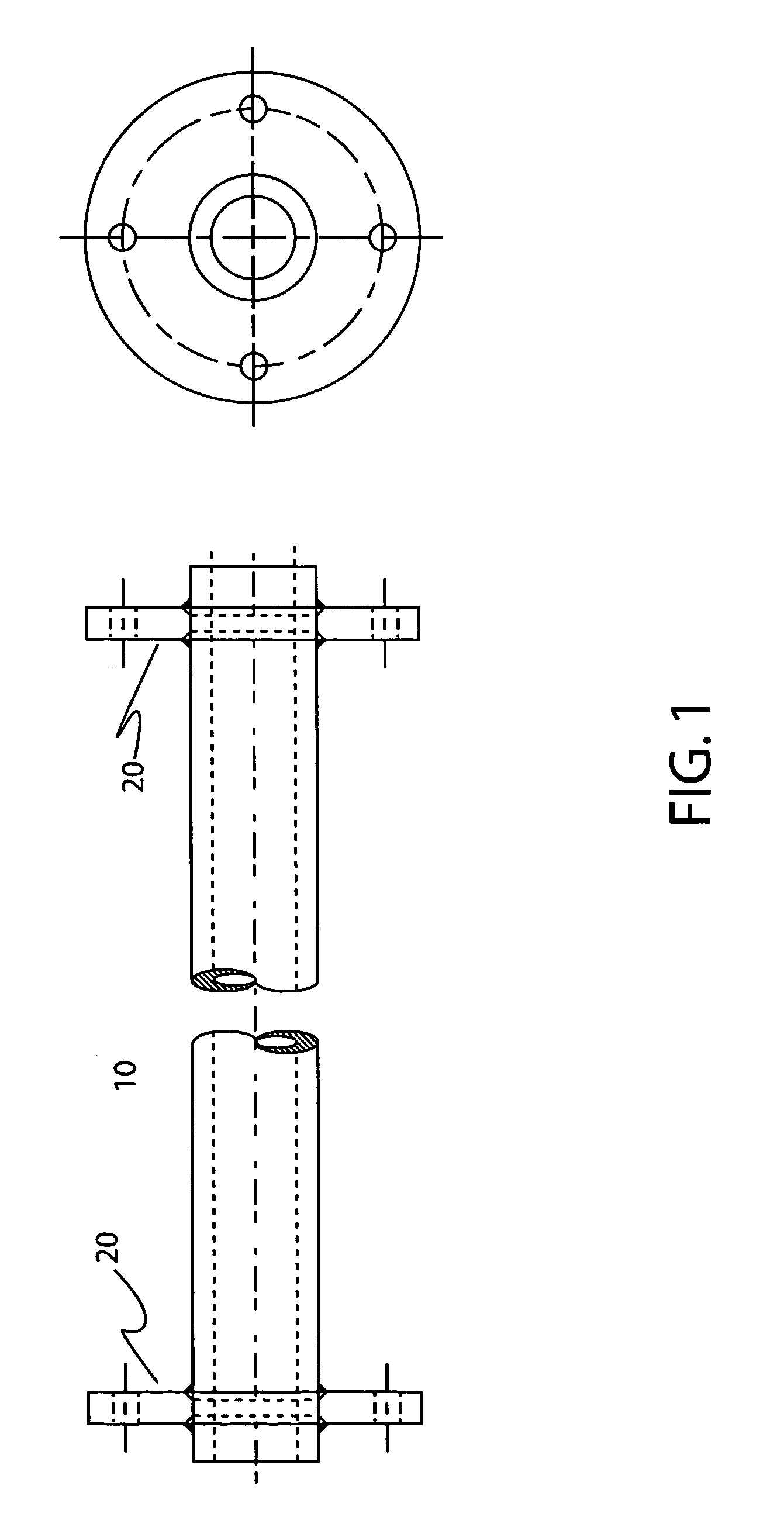
[0018]FIG. 1 is a truncated side elevational view of a length of tube along the longitudinal axis.

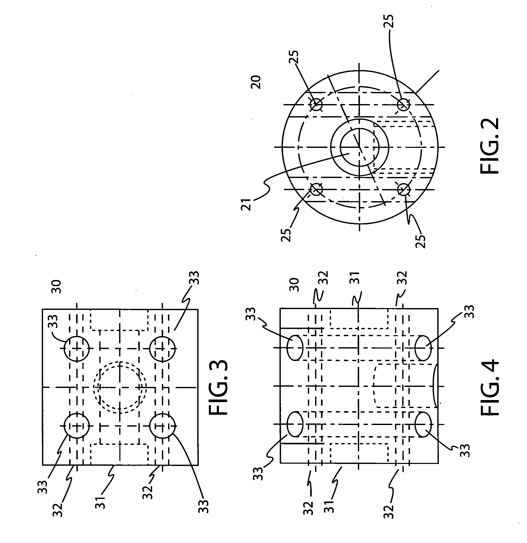
[0019]FIG. 2 is a front elevational plan view of the flange.

[0020]FIG. 3 is a top plan view of the connector in the cleaning and pickling portion of the apparatus.

[0021]FIG. 4 is the front elevational plan view of the connector cleaning and pickling portion of the apparatus.

[0022]FIG. 5 is a top plan view of the connector in the electroplating portion of the apparatus.

[0023]FIG. 6 is a partly in sectional front elevational view of the connector in the electroplating portion of the apparatus.

[0024]FIG. 7 is a front plan view of the flange in the assembled apparatus.

[0025]FIG. 8 is a sectional view of the connector in the electroplating portion of the apparatus along line A-A of FIG. 7.

[0026]FIG. 9 is a top plan view of dowel.

[0027]F...


PUM

PropertyMeasurementUnit
Lengthaaaaaaaaaa
Electrical conductivityaaaaaaaaaa
Diameteraaaaaaaaaa

Abstract

A continuous electro-cleaning, pickling and electroplating apparatus and method using a plurality of elongate tubes that are electrically conductive.

Description

CROSS REFERENCE TO RELATED APPLICATION[0001]This patent application is related to and claims priority from U.S. Provisional Patent Application Ser. No. 61 / 063,930 filed Feb. 7, 2008.FIELD OF THE INVENTION[0002]The present invention relates, in general, to electroplating and cleaning and, more particularly, this invention relates to a continuous electroplating and cleaning apparatus.BACKGROUND OF THE INVENTION[0003]Prior to the conception and development of the present invention, as is generally well known in the prior art, electroplating is typically performed in a batch operation. The same is true of electro-cleaning.[0004]Electroplating requires a prepared surface. In practice, this surface preparation is governed, for example, by ASTM B322. One of the processes used to clean the electroplated surface is electro-cleaning.[0005]The process of electro-cleaning is immerse the piece as an anode in an appropriate solution such as an alkaline salt in an electrolytic cell and to apply a ...

Claims


Application Information

Patent Timeline
IPC IPC(8): C25D7/00C25F7/00C25D17/00C25F1/04
CPCC25F7/00C25D17/00
Inventor ALTMAN, SHMUEL
Owner ALTMAN SHMUEL
Features
  • Generate Ideas
  • Intellectual Property
  • Life Sciences
  • Materials
  • Tech Scout
  • Unparalleled Data Quality
  • Higher Quality Content
  • 60% Fewer Hallucinations
Learn More