Robot controller having component protecting function and robot control method

a robot controller and component technology, applied in the field of robot controllers, can solve the problems of component damage, abnormality cannot be effectively detected, and each component of the robot such as the reducer or the cable may not be sufficiently protected, so as to reduce the load torque of each axis of the robo

Inactive Publication Date: 2009-08-13
FANUC LTD
View PDF16 Cites 26 Cited by
  • Summary
  • Abstract
  • Description
  • Claims
  • Application Information

AI Technical Summary

Benefits of technology

[0008]Accordingly, an object of the present invention is to provide a robot controller and a robot control method, by which each element or component constituting a robot is protected.
[0013]The processing part may stop the motion of the robot when the abnormality is detected. Alternatively, the processing part may decelerate the motion of the robot when the abnormality is detected. Otherwise, the processing part may move the robot in a direction for a certain period of time such that the load torque of each axis of the robot decreases.

Problems solved by technology

However, even when such a function is used to detect a collision or the like and stop the motor, each component of the robot such as a reducer or a cable may not be sufficiently protected.
In such a case, an abnormality cannot be effectively detected by a method of the prior art, whereby the component may be damaged.
In the prior art, even when collision does not occur (i.e., a robot is normally operated), it is not assured that torque applied to each component does not exceed a range within which the torque cannot damage the component.

Method used


Image

  • Robot controller having component protecting function and robot control method
  • Robot controller having component protecting function and robot control method
  • Robot controller having component protecting function and robot control method

Examples


Embodiment Construction

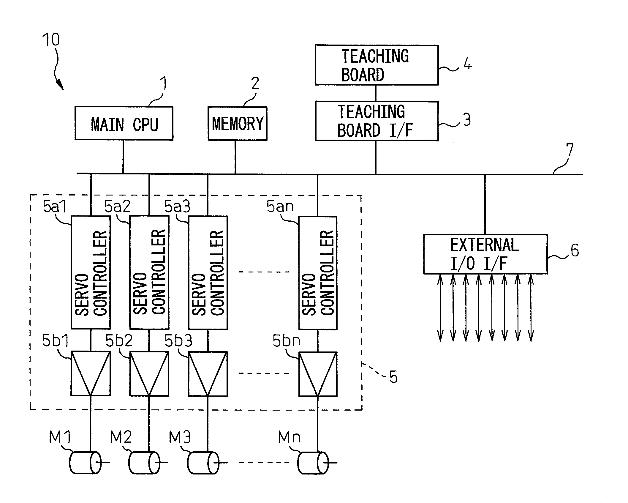
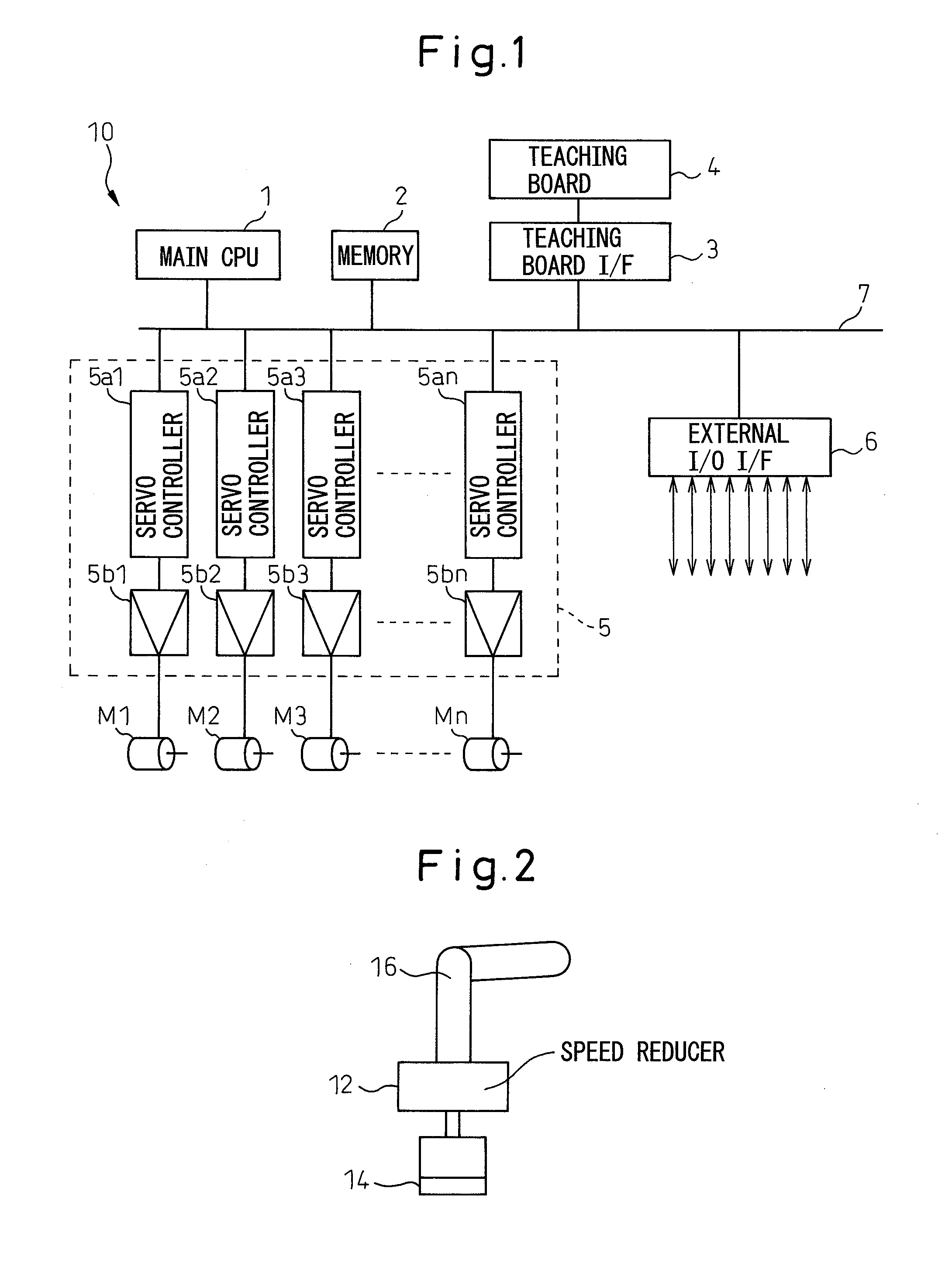
[0024]FIG. 1 shows a block configuration showing substantial parts of a robot controller according to one embodiment of the invention. Robot controller 10 has a main CPU 1, a memory 2 including a RAM (random access memory), a ROM (read-only memory) and a non-volatile memory (EEPROM or the like), a teaching board interface 3, a servo control unit 5 and an I / O interface 6 for external units, which are connected each other via a bus 7. Robot controller 10 also has a teaching operation board 4 connected to teaching board interface 3.

[0025]A system program, for supporting the basic function of robot controller 10 and a robot (not shown) to be controlled by the robot controller, is stored in the ROM of memory 2. The motion program of the robot taught according to the application and relevant set data are stored in the non-volatile memory of memory 2. The RAM of memory 2 is used for a storage area to temporarily store various data processed by main CPU 1.

[0026]Servo control unit 5 has a pl...


PUM


Abstract

A robot controller and a robot control method, by which each element constituting a robot is protected. An output of a rotary encoder attached to a servomotor is read, and the motor speed is obtained by calculating the difference between a current speed and another speed in a previous speed loop. Then, a processor of the servo controller of each link of a robot arm executes a normal speed loop control in order to calculate a torque command of the motor. Next, a load torque is estimated by using the obtained torque command and the motor speed, and the estimated load torque in each speed loop is compared with a predetermined threshold. If the load torque is larger than the threshold in at least one of the axes, the robot controller judges that an abnormality has occurred in the robot, generates an alarm or warning, and then controls the robot so as to protect the element.

Description

RELATED APPLICATIONS[0001]The present application claims priority from Japanese Patent Application No. 2008-29355, filed on Feb. 8, 2008, the entire content of which is fully incorporated herein by reference.BACKGROUND OF THE INVENTION[0002]1. Field of the Invention The present invention relates to a robot controller for controlling a multi-joint robot (hereinafter, referred to as “a robot”), and in particular, a robot controller having a function for protecting each component of the robot and a control method of the robot.[0003]2. Description of the Related Art[0004]As a function for protecting a robot from overload, a collision detecting function is known. For example, Japanese Unexamined Patent Publication No. 11-15511 discloses a technique for estimating a disturbance applied to a motor for driving each axis of a robot and judging that a collision occurs if an estimated value is larger than a predetermined threshold.[0005]Japanese Unexamined Patent Publication No. 2005-186183 di...

Claims


Application Information

Patent Timeline
Patent Type & Authority Applications(United States)
IPC IPC(8): G05B9/02
CPCB25J9/1674G05B2219/39237G05B2219/39261G05B2219/41381G05B2219/41367G05B2219/41373G05B2219/40525
Inventor KATO, TETSUAKIINAGAKI, SHOUGO
Owner FANUC LTD
Why Eureka
Try Eureka