Method of forming an article

a technology of article and forming method, which is applied in the direction of additive manufacturing, additive manufacturing with solids, additive manufacturing process, etc., can solve the problems of increasing the difficulty of subsequent processing of unmelted powder, affecting the quality of finished products, so as to reduce the lateral force

Active Publication Date: 2009-08-13
SIEMENS ENERGY GLOBAL GMBH & CO KG
View PDF18 Cites 34 Cited by
  • Summary
  • Abstract
  • Description
  • Claims
  • Application Information

AI Technical Summary

Benefits of technology

[0036]This alignment in particularly beneficial because it reduces any lateral forces applied to the walls by the blade.

Problems solved by technology

In these methods whilst it is possible to build complex parts it is however not possible to commence the building of a part in the bulk of a powder bed or free space—the powder must be melted and fused to a solid structure.
This unmelted powder presents numerous problems to subsequent processing.
Firstly, to remove the stresses inherent in the as-built part a thermal process is needed for all but the smallest parts (such as dental inlays) whilst the part is still firmly attached to the platen.
Secondly, to cut the part from the platen may require a wire Electrical Discharge Machining (EDM) process, particularly for hard alloys such as cobalt chrome.
Loose powder contained within voids shorts out the wire in the EDM process presenting significant difficulties and additional costs for this process.
Thirdly, if cutting with a saw, lubricant may be used and the loose powder then mixes with the lubricant creating difficulties.
Fourthly, the metal powder may be hazardous to health, or valuable (such as in the case of titanium alloys).
In particular it should also be understood that the laser sintering / melting process is not capable of making any and all structures and in particular cannot reliably make free standing thin pillars.

Method used


Image

  • Method of forming an article
  • Method of forming an article
  • Method of forming an article

Examples


Embodiment Construction

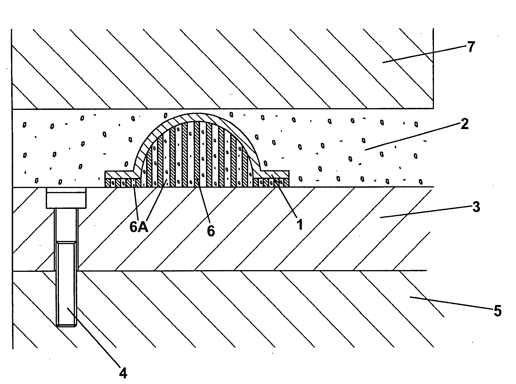
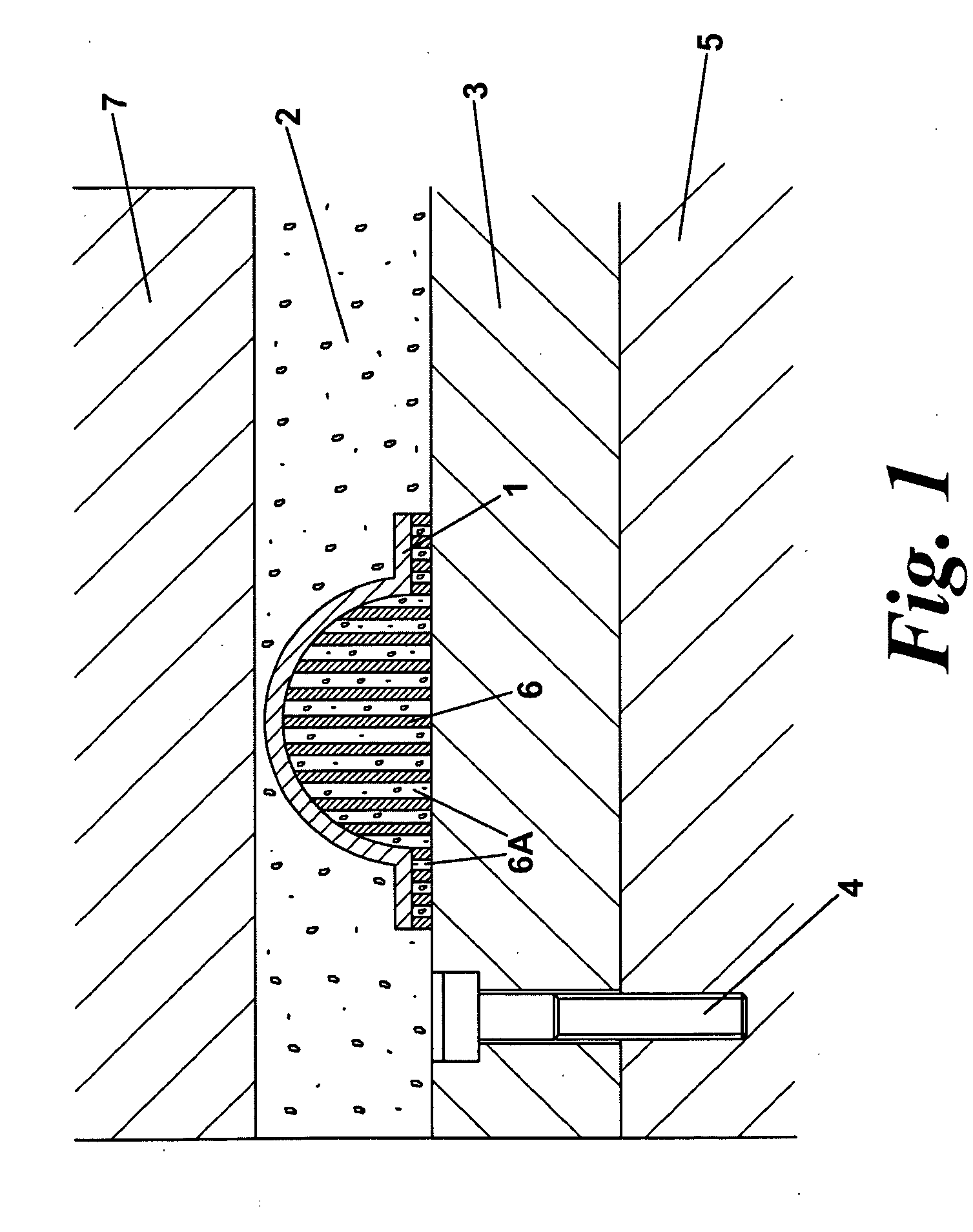
[0061]FIG. 1 is a diagrammatic view at the completion of the build of a solid object 1 formed by the solidification of powder 2 by the application of a point source of heat (not shown) in a layer wise process. The building commences at a platen 3 bolted by bolt 4 to an elevator platform 5 within a powder bed machine. To enable the solid object to be built and allow a cutting gap between the object and the platen a support structure is needed. The support structure of the invention is shown at 6 being a solid support with grooves or channels 6a that contain loose powder 2. The grooves or channels are orientated such that they line along the line of traverse of the powder recoater blade 7. The grooves or channels are open at least one end so that powder can be removed from them, e.g. by vacuum, prior to heat treatment of the article or object 1.

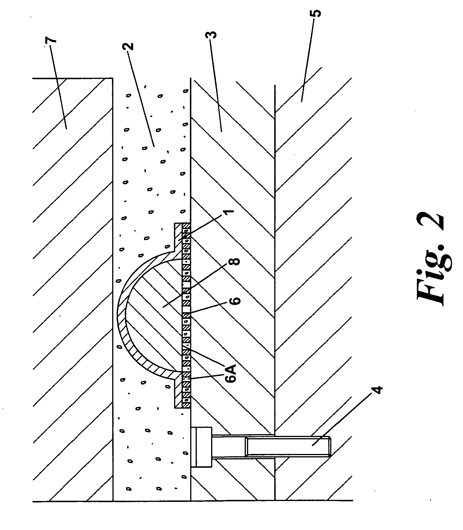
[0062]FIG. 2 again shows a support structure of an embodiment of the invention at 6 as a discrete layer below a support structure 8 of the pri...


PUM

PropertyMeasurementUnit
mean diameteraaaaaaaaaa
widthaaaaaaaaaa

Abstract

From one aspect, a method of forming a support for use in a selective sintering or melting process includes forming a body on a platen having a plurality of generally parallel channels each channel being open at least one end. The base of the channels may be formed by the platen. Preferably the support is formed by a selective sintering or melting process.

Description

BACKGROUND AND SUMMARY[0001]This invention relates to a method of forming an article.[0002]The laser or electron beam sintering / melting of powdered materials to form solid parts is now well known—though not so well known as for there to be an established nomenclature. In particular there are commercial powder bed ‘Selective Laser Sintering’ / ‘Selective Laser Melting’ (SLS / SLM) machines such as the M270 produced by Electron Optical Systems (EOS) M270 and the Realizer II marketed by MCP. These take metal powders under an inert atmosphere and direct a CO2 or fibre laser onto a layer of powder.[0003]There are also other similar powder bed machines sometimes using an electron beam and somewhat related processes where there is no bed of powder, but the powder is ejected from a nozzle proximate the laser such as in the Trumpf DMD 505. These processes are called such things as ‘Direct Laser Fabrication’ or ‘Direct Metal Deposition’.[0004]In the ‘powder bed’ processes a point source of energy...

Claims


Application Information

Patent Timeline
Patent Type & Authority Applications(United States)
IPC IPC(8): B22F3/10
CPCB22F3/1055B22F2998/00B29C67/0077B22F3/003B29C64/153Y02P10/25B22F10/28B22F10/66B22F10/47B22F10/64B22F12/67
Inventor ILLSTON, TREVOR JOHN
Owner SIEMENS ENERGY GLOBAL GMBH & CO KG
Why Eureka
Try Eureka