
High-speed backplane connector

a backplane connector and high-speed technology, applied in the direction of coupling device connection, coupling protective earth/shielding arrangement, two-part coupling device, etc., can solve the problems of alignment still exist, limit performance, cross-talk

Active Publication Date: 2009-08-13
TYCO ELECTRONICS LOGISTICS AG (CH)
View PDF3 Cites 37 Cited by
  • Summary
  • Abstract
  • Description
  • Claims
  • Application Information

AI Technical Summary

Benefits of technology

[0008]An advantage of the present disclosure is that the contact pairs are shielded electrically and mechanically to provide the ability to operate at high-speed with protection against electromagnetic interference and physical damage to the contact pairs.
[0009]Another advantage is that grounding may be achieved with fewer connections to the circuit boards, providing additional space for additional pairs and / or wiring.
[0010]Another advantage is that the mesh contact member provides alignment and signal continuity between printed circuit boards, particularly when exposed to rugged and / or extreme environmental conditions.

Problems solved by technology

Electronic equipment, such as that used in military applications, is often required to be operated in rugged, extreme environmental conditions.
While the flex circuits may provide easier access for the soldering, problems with alignment still exist.
In addition, the flex circuit has long tails that act like antennae, which tails create interference and limit performance as described above.
In addition other conventional connectors provide little or no shielding from adjacent wires, resulting in cross talk and decreased data transfer speed.

Method used


Image

  • High-speed backplane connector
  • High-speed backplane connector
  • High-speed backplane connector

Examples


Embodiment Construction

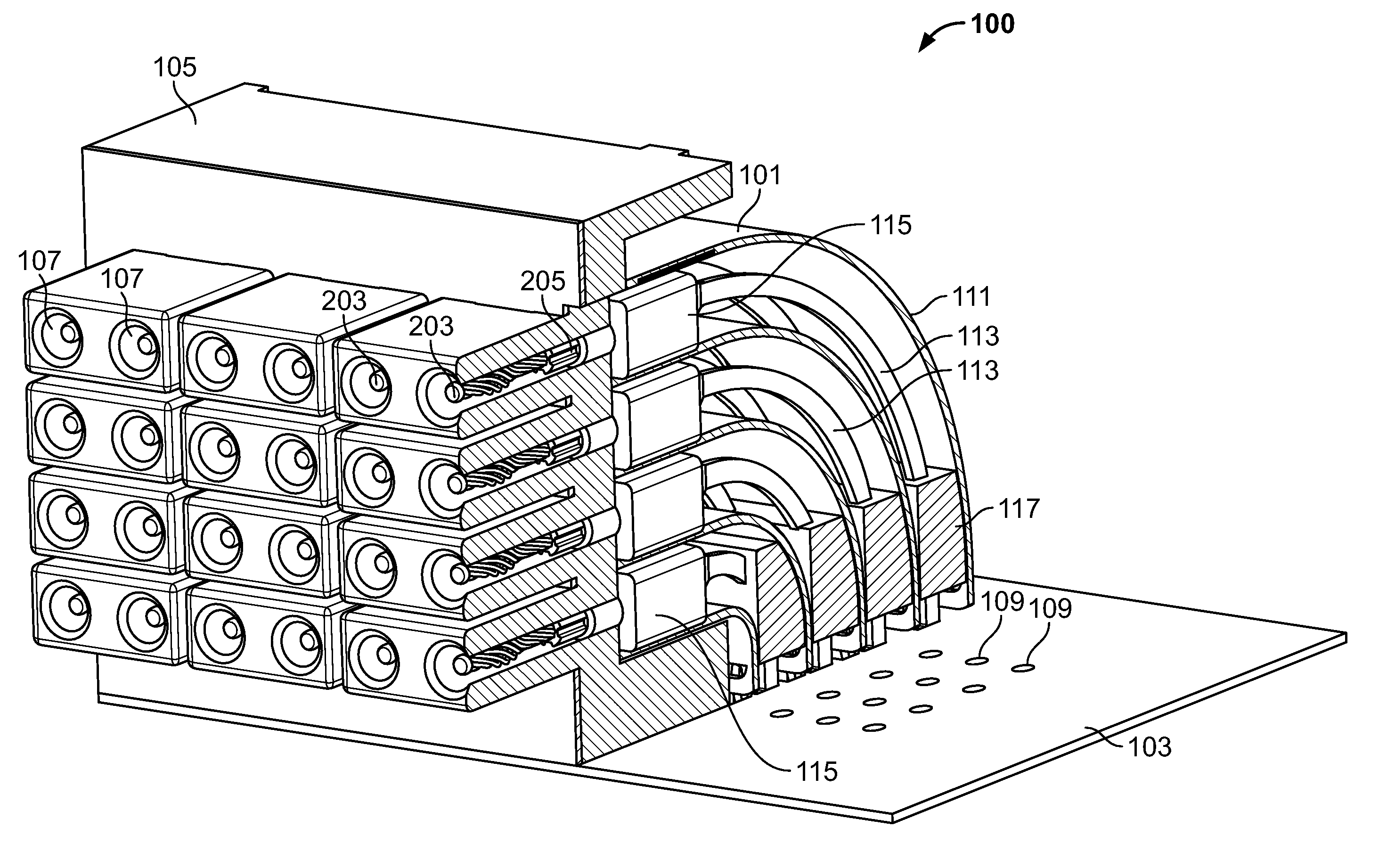
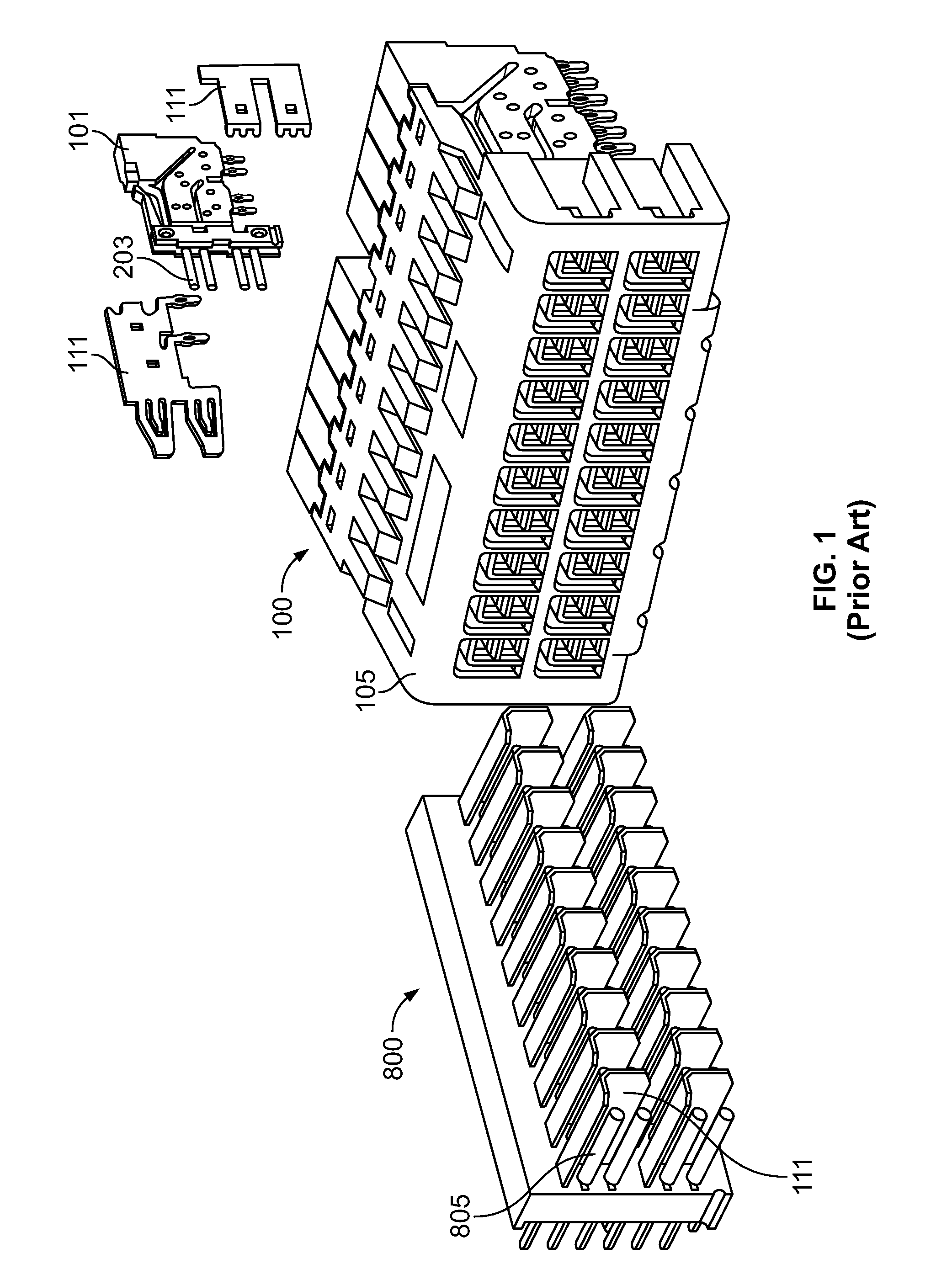
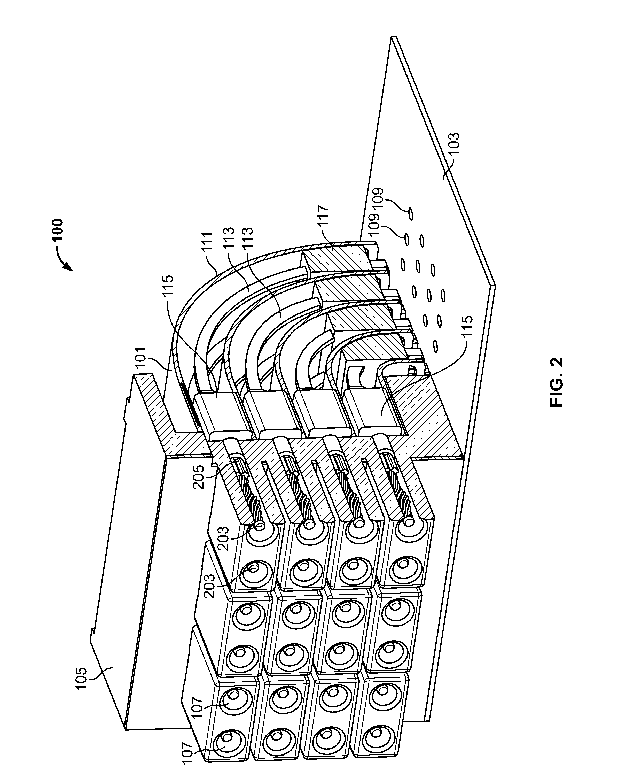
[0032]FIG. 1 shows a partially exploded view of a known connector system 100 and backplane 800. As shown, the connector system 100 includes the terminal modules 101 arranged within the terminal housing 105, as shown and described above with respect to FIG. 1. In addition, in this embodiment, cross-talk shielding members 111 are provided and disposed between adjacent modules 101 to resist or prevent cross-talk between modules 101. The cross-talk shielding members 111 upon engagement between the connector system 100 and the backplane 800 may be utilized to shield the signal contacts from signals within adjacent modules 101 and may include any structures known in the art for providing electrical shielding. Housing module 105 includes a plurality of socket receiving apertures 107 configured to receive sockets of a backplane 800. The terminal modules 101 connect to the PCB 103 via first contact portion 201 engaged with opening 109 in the PCB 103. The terminal modules 101 include second c...


PUM


Abstract

A terminal module for assembly into a high-speed electrical connector having a contact receiving first contact pair and second contact pair, the second contact pair being in electrical communication with the first contact pair via a corresponding pair of contact interconnections. The contact interconnections have a substantially identical length of the corresponding pair and are arranged within parallel planes. The module further includes a shielding member arranged and disposed in close proximity to at least three edges of one or more of the first contact pair, the second contact pair and the contact interconnections to provide shielding. A housing member is arranged and disposed to receive backplane contacts via contact receiving apertures. The housing member is engaged with the first contact pair to receive the contacts into the contacts of the first contact pair. A backplane having grounding plate grid is also disclosed.

Description

FIELD OF THE INVENTION[0001]The present disclosure is directed to electrical connectors. In particular, the disclosure is directed to high-speed electrical connectors for connecting circuit boards.BACKGROUND OF THE INVENTION[0002]Electronic equipment, such as that used in military applications, is often required to be operated in rugged, extreme environmental conditions. Examples of such conditions include excessive moisture, salt, heat, vibration, mechanical shock, and electromagnetic interference (EMI). To function cooperatively, some type of connector is required so that when two printed circuit boards are brought into electrical contact with one another, the boards function as a single board when inserted into a backplane board or other module of a larger electronic piece of equipment.[0003]Other conventional connectors include a two-piece connector using so-called flex circuits extending from the printed circuit boards. These flex circuits must be soldered to the printed circui...

Claims


Application Information

Patent Timeline
Patent Type & Authority Applications(United States)
IPC IPC(8): H01R13/648H01R12/71
CPCH01R13/514H01R12/724H01R23/688H01R13/6471H01R13/6585H01R12/00
Inventor NGUYEN, HUNG THAIFULPONI, JOHN A.YOHN, BRENT DAVID
Owner TYCO ELECTRONICS LOGISTICS AG (CH)
Learn More