
Combined cycle missile engine system

Active Publication Date: 2009-08-20
AEROJET ROCKETDYNE INC
View PDF24 Cites 34 Cited by
  • Summary
  • Abstract
  • Description
  • Claims
  • Application Information

AI Technical Summary

Benefits of technology

[0013]In accordance with a second embodiment of the invention, an insensitive combined cycle missile propulsion system includes a fuel contained within a first section of the missile and an oxidizer contained within a second section of the missile where one of the fuel or oxidizers is a liquid until consumed during flight and the other is a solid until consumed during flight. A first conduit has a first valve communicating the fuel and the oxidizer and a second conduit, spatially removed from the first conduit, has a second valve communicating the fuel and the oxidizer. A rocket nozzle downstream of the first valve and the second valve is effective to exhaust combustion products resulting from combustion of the fuel and the oxidizer into an after burner. An obstructed air inlet has a nose end and a body end with the body end terminating at the combustor.

Problems solved by technology

Conventional rocket propulsion systems to propel missiles have performance limitations imposed by a number of factors including a requirement to transport a required amount of oxidizer.
For a given take-off mass this results in shorter range powered flights or reduced payloads relative to systems like ramjets and scramjets which obtain the oxidizer from atmospheric air.
Ramjet and scramjet engines have their own limitations; including inadequate thrust at low speeds thereby requiring a rocket or turbine booster of significant mass to accelerate the missile to ramjet takeover speed.
Liquid bi-propellant rocket systems separate the fuel and oxidizer until injected into the rocket motor but have a risk of leakage and fire if the tanks are breached by accident or enemy action.
Accidental ignition of the propellant(s) that can cause severe hazards for the user of the weapon.
These hazards include explosion, fire or even uncommanded flight of the missile.

Method used


Image

  • Combined cycle missile engine system
  • Combined cycle missile engine system
  • Combined cycle missile engine system

Examples


first embodiment

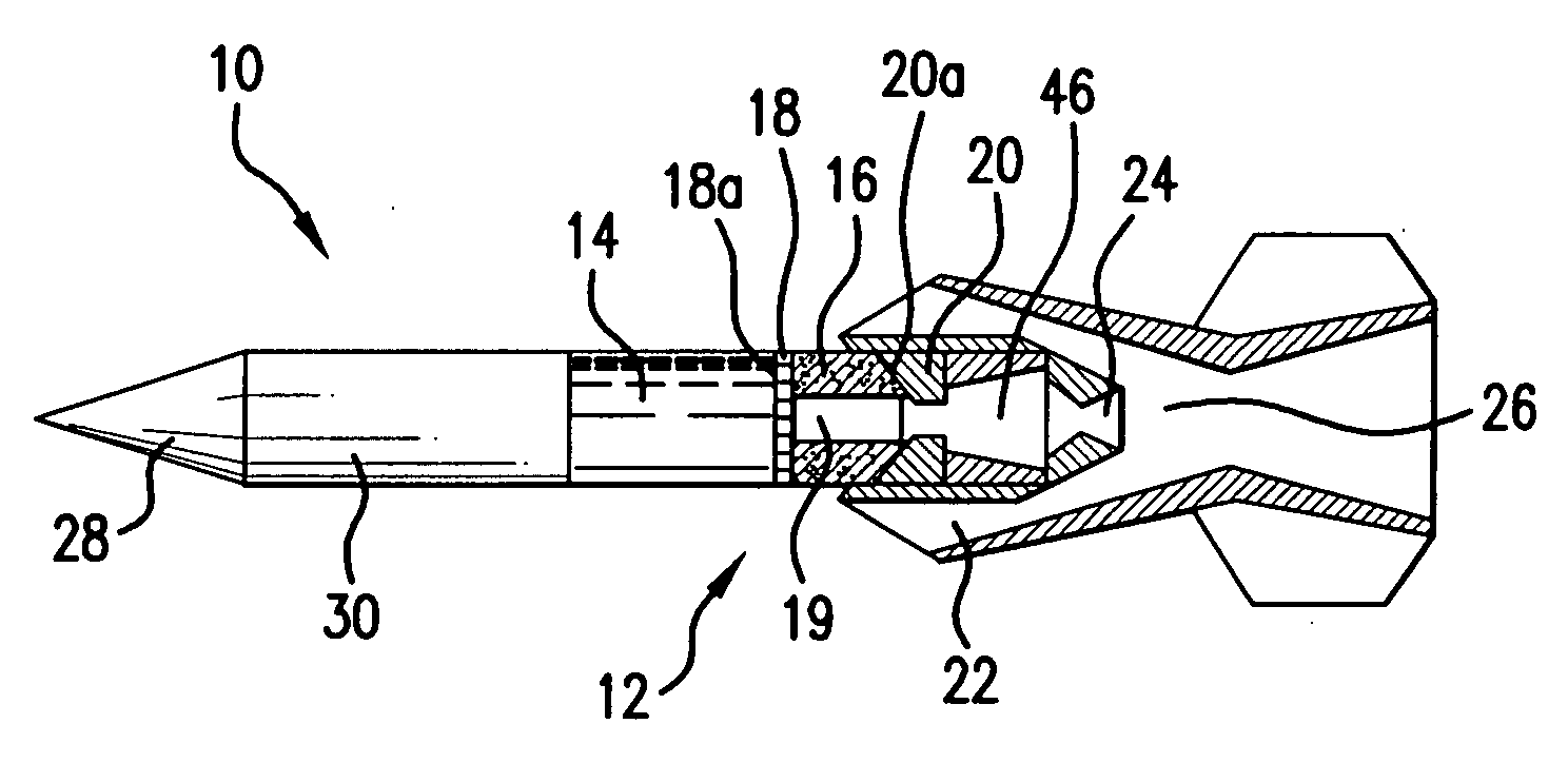
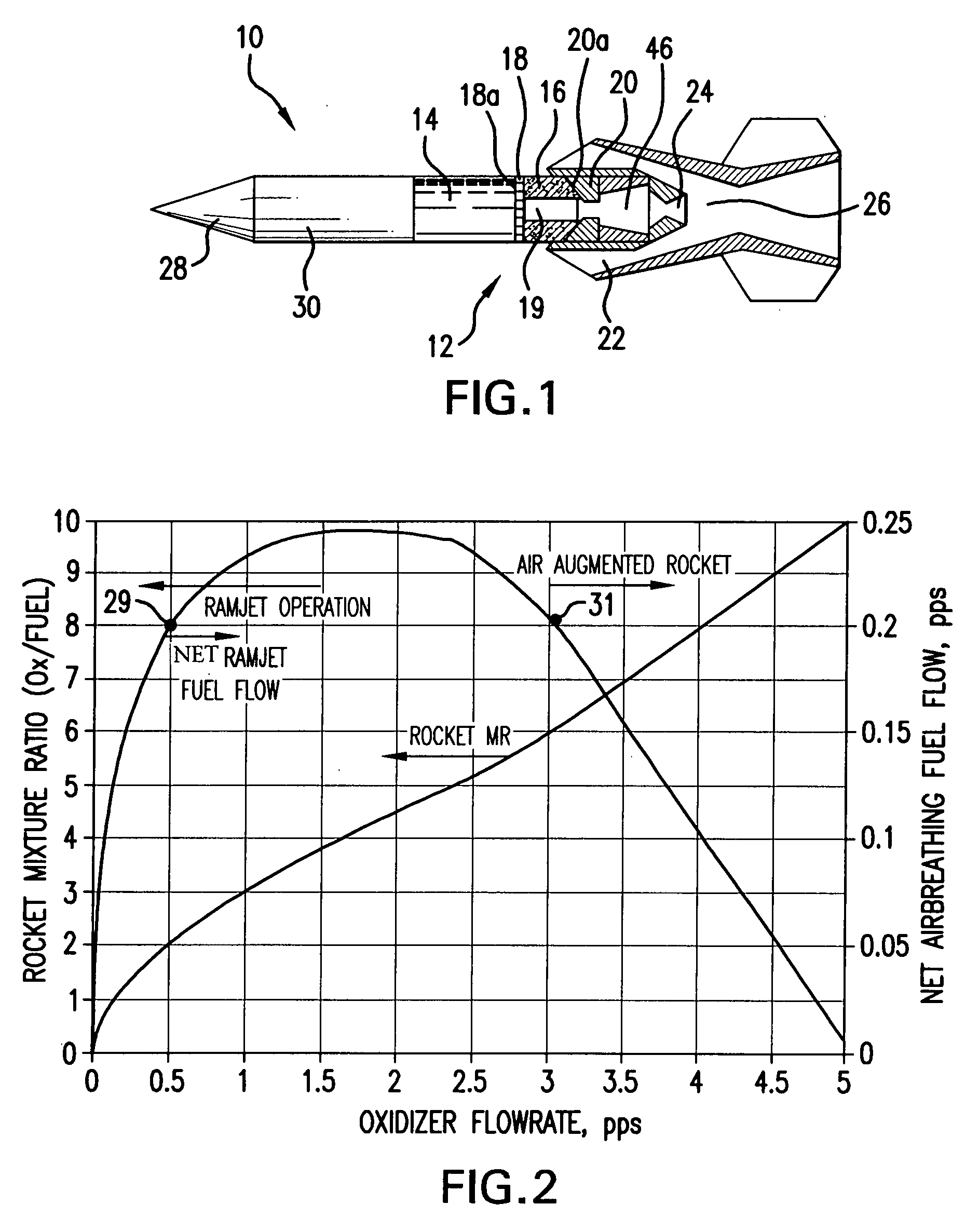
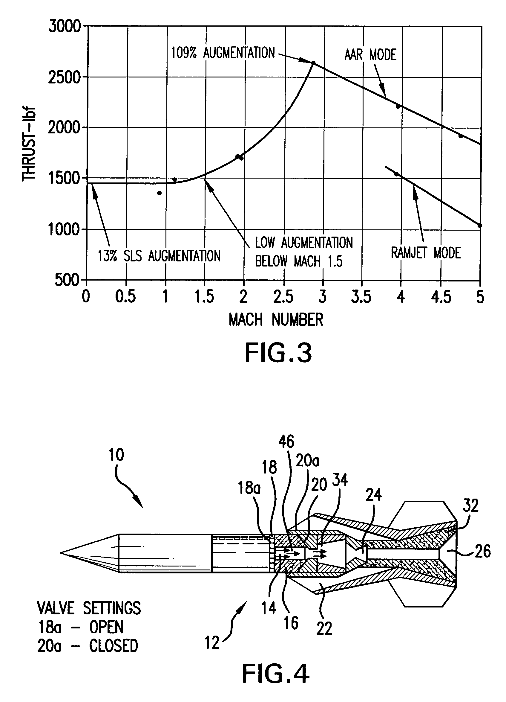
[0047]FIG. 4 shows the motor 12 in integral reverse hybrid rocket (IRHR) mode of operation in accordance with the This mode is used for initial acceleration of the missile 10 up to a speed where the second mode, the air augmented hybrid rocket mode, can be efficiently operated. The propulsion system is initiated by opening the forward liquid oxidizer injector 18a control valve and the liquid oxidizer 14 is sprayed onto the solid fuel 16. Ignition is by any of a number of conventional means such as a small pyrotechnic squib or catalysts exposed to the oxidizer flow. Once ignited, the combustion of the fuel in the hybrid gas generator 46 creates a very fuel-rich hot exhaust gas 34 that passes over submerged aft liquid oxidizer injector 20 and into the primary rocket nozzle 24 where the gases are accelerated to a low supersonic velocity and enter the ramjet combustor 26 initially filled with oxidizer rich boost propellant 32. The contact of the hot fuel-rich exhaust gases 34 with the ...

second embodiment

[0055]FIG. 9 shows a missile 10 propelled by an engine 12 in accordance with the second embodiment in a fractional IRHR mode of operation, as would be employed to initiate a mission. Hybrid engine 12 includes liquid oxidizer 14 and solid fuel 16. A central rocket chamber 38 includes downstream liquid oxidizer injector 40. Upstream liquid oxidizer injector 42 is disposed between liquid oxidizer 14 and solid fuel 16. Air inlets 22, that extend from a nose end 43 to a body end 45, terminate at a centerline scramjet combustor 48. The air inlets 22 are initially blocked by an air inlet cover 44.

[0056]The propulsion system is initiated by opening the upstream liquid oxidizer injector 42 control valve and the liquid oxidizer 14 is sprayed into an annular hybrid gas generator 46 with multiple ports for gas generation and flow. Ignition is as before. Once ignited, the combustion of the fuel in the annular hybrid gas generator 46 creates very fuel-rich hot exhaust gases 34 that flow forward a...


PUM


Abstract

An insensitive combined cycle missile propulsion system includes a solid fuel contained within a first section of the missile, a liquid oxidizer contained within a second section of the missile and a solid oxidizer contained within a third section of said missile. A first conduit has a first valve communicating the fuel and the oxidizer and a second conduit, spatially removed from the first conduit, has a second valve communicating the fuel and the oxidizer. An inlet system for delivering atmospheric oxygen for combustion with the fuel rich gases generated within the missile and a nozzle exhausts combustion products that result from combustion of the fuel, the liquid and solid oxidizers, and air.

Description

CROSS REFERENCE TO RELATED APPLICATION(S)[0001]This patent application claims priority to U.S. Provisional Patent Application Ser. No. 60 / 858,032 titled “Combined Cycle Missile Engine System” that was filed on Nov. 10, 2006. The subject matter of that provisional patent application is incorporated herein in its entirety.U.S. GOVERNMENT RIGHTS[0002]N.A.BACKGROUND[0003]1. Field[0004]This invention relates to a propulsion system for a missile. More particularly, the invention relates to a system for separating and controlling oxidizer and fuel in an insensitive missile propulsion system, thereby enabling efficient operation in each one of the multiple modes of operation utilized by the missile during a flight.[0005]2. Description of the Related Art[0006]Conventional rocket propulsion systems to propel missiles have performance limitations imposed by a number of factors including a requirement to transport a required amount of oxidizer. For a given take-off mass this results in shorter ...

Claims


Application Information

Patent Timeline
IPC IPC(8): C06B45/10F02K9/28
CPCF02K7/10F42B15/10F02K9/763F02K7/18
Inventor BULMAN, MELVIN J.SIEBENHAAR, ADAM
Owner AEROJET ROCKETDYNE INC
Learn More