Electronically-controlled throttle body

Inactive Publication Date: 2009-08-20
MITSUBISHI ELECTRIC CORP
View PDF5 Cites 19 Cited by
  • Summary
  • Abstract
  • Description
  • Claims
  • Application Information

AI Technical Summary

Benefits of technology

[0010]The present invention has been made to resolve problems as described above, and aims at providing an electronically-controlled throttle body in which the inter-shaft distance between the motor shaft and the

Problems solved by technology

However, in a conventional electronically-controlled throttle body as described above, since torque is transmitted by the spur gear two-stage reduction gear mechanism, inter-shaft distances each are needed between the output gear shaft and the intermediate gear shaft and between the intermediate gear shaft and the input gear shaft, depending on each gear's pitch radius; therefore, the size of device is determined by those inter-shaft distances, causing a problem in that the device can not be easily downsized.
Moreover, trying to downsize the device needs to limit the pitch radius of each gear, which needs to limit the number of teeth of each gear accordingly; thereby, it becomes difficult to increase reduction gear ratios, resulting in necessary motor driving torque being greater, which has been an inhibiting factor of downsizing the motor.
Moreover, when a spur-gear two-stage reduction gear mechanism is used for the reduction gear mechanism, the output gear fixed on the motor shaft undergoes reaction force from the intermediate gear; the reaction force generates to the motor shaft bending moment whose fulcrum lies on a bearing of the motor shaft; consequently, the m

Method used


Image

  • Electronically-controlled throttle body
  • Electronically-controlled throttle body
  • Electronically-controlled throttle body

Examples


Example

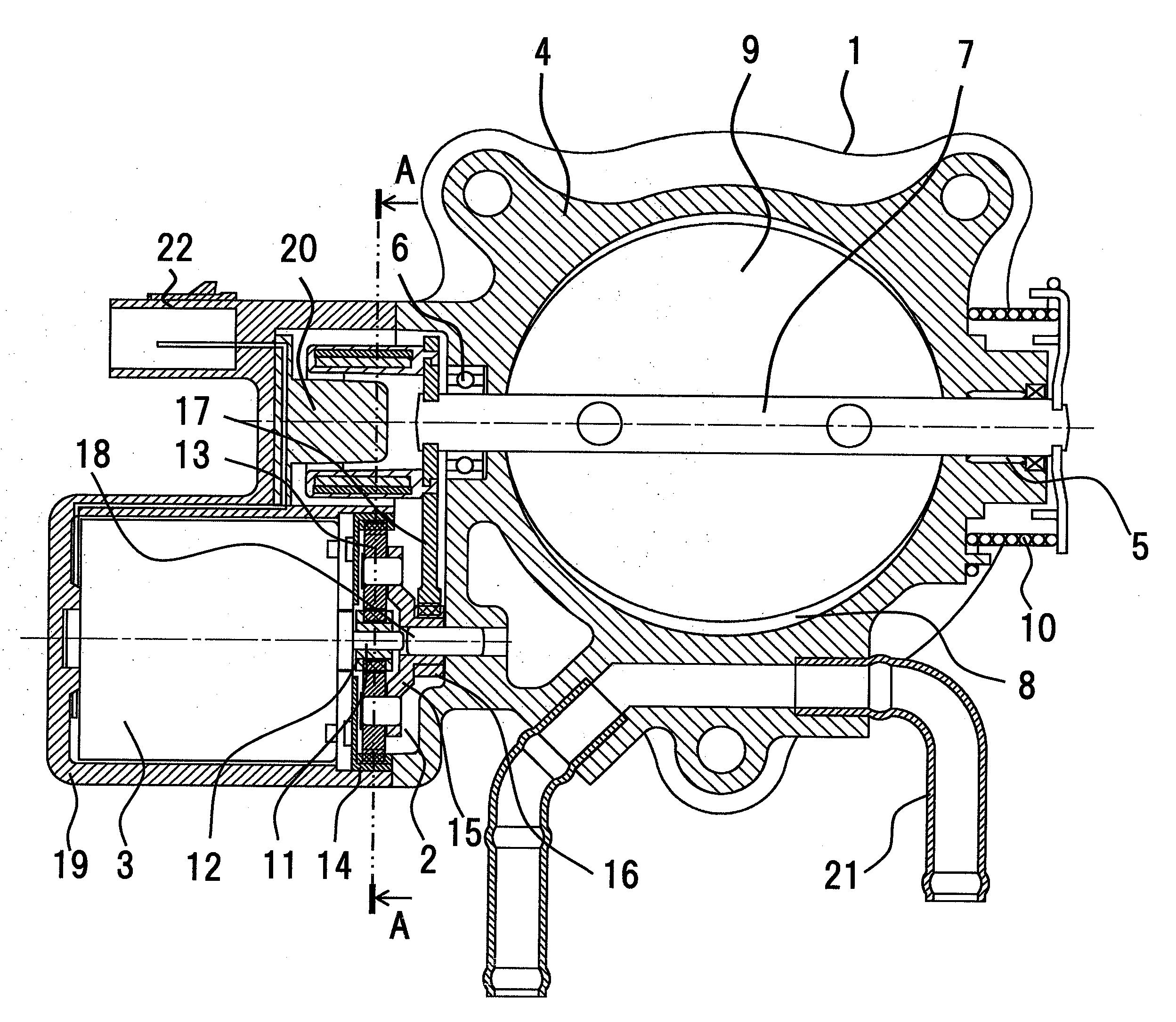
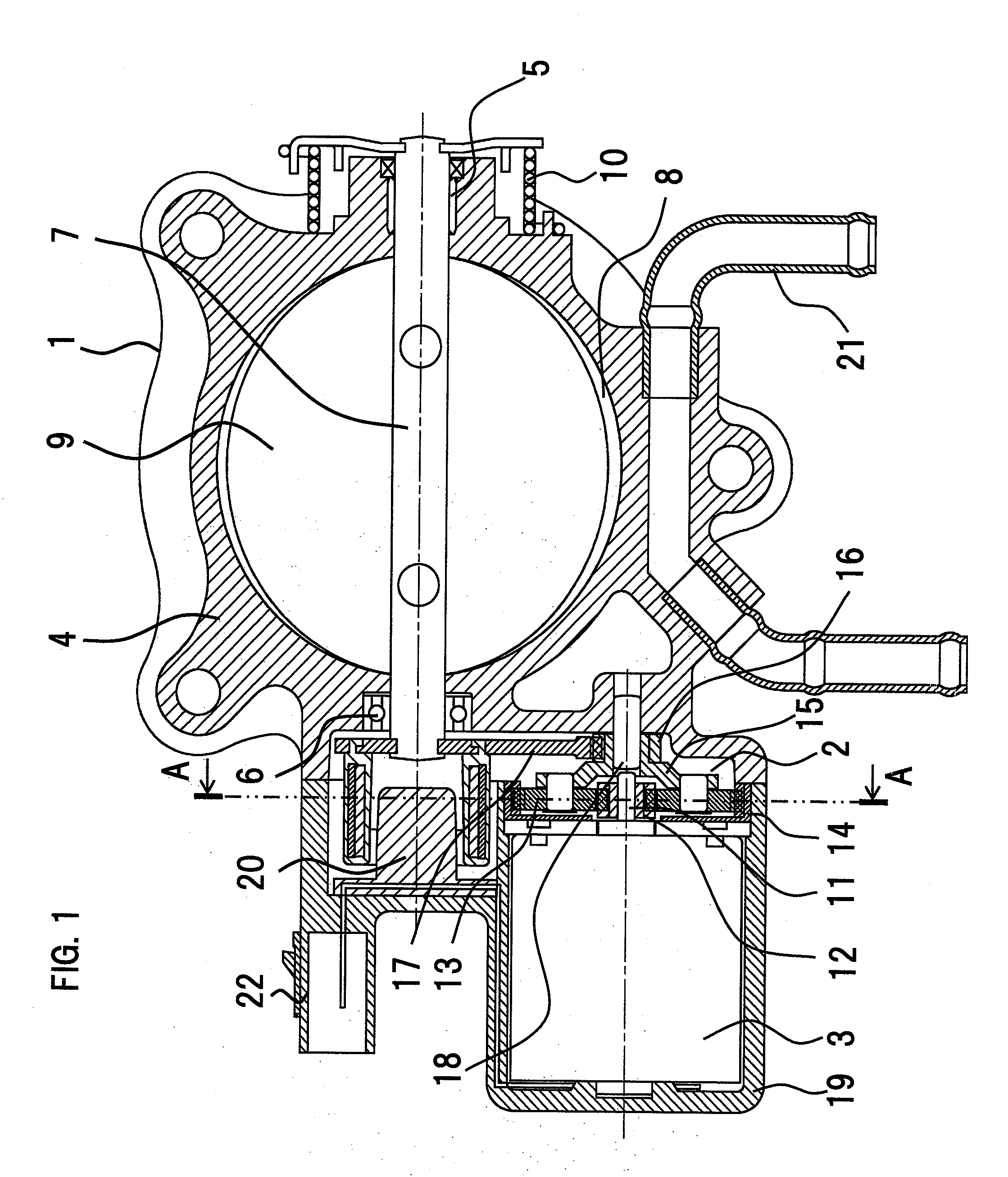
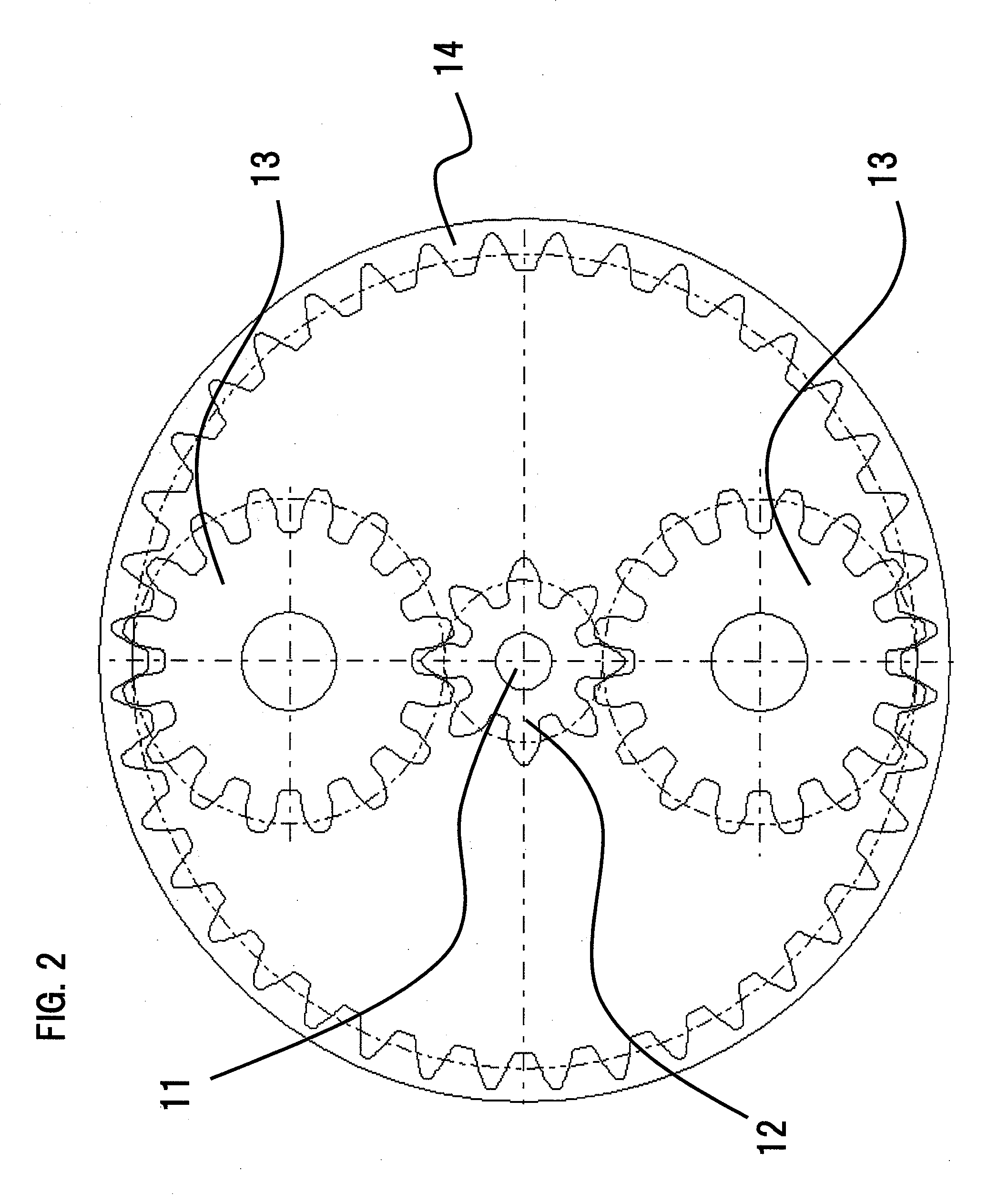
[0021]Hereinafter, Embodiment 1 of the present invention will be explained referring to FIG. 1 and FIG. 2. Here, parts that have the same reference numerals in each figure represent the same or corresponding ones. FIG. 1 is a cross-sectional view showing an electronically-controlled throttle body according to Embodiment 1 of the present invention; FIG. 2 is a partial cross-sectional view along the A-A line in FIG. 1. In FIG. 1 and FIG. 2, the electronically-controlled throttle body includes a throttle valve 1, a reduction gear mechanism 2 connected to the throttle valve 1 and a motor 3 connected to this reduction gear mechanism 2.

[0022]The throttle valve 1 includes a body 4, a valve shaft 7 that is rotatably supported by the right and left walls of the body 4 via a first bearing 5 and a second bearing 6, a valve disc 9 that is fixed on the valve shaft 7 and varies an opening area of an air-intake passage 8 formed in the body 4, and a spring 10 that is provided in the proximity of th...

Example

Embodiment 2

[0035]FIG. 3 is a cross-sectional view showing an electronically-controlled throttle body according to Embodiment 2 of the present invention. In the figures, parts that have the same reference numerals in FIG. 1 and FIG. 2 represent the same or corresponding ones, eliminating duplicate explanations.

[0036]In the electronically-controlled throttle body according to Embodiment 2, the body 4 is molded out of resin (PPS) and the holder 23 made of brass is insert-molded into the body 4. The bearing 6 that supports the valve shaft 7 and the pin 18 that supports the smaller gear 16 are press-inserted into the holder 23.

[0037]According to Embodiment 2, since the number of gear shafts is less by one than that of a conventional electronically-controlled throttle body provided with a spur-gear two-stage reduction gear mechanism, and the number of locations where high inter-shaft accuracy is needed is also less, necessary dimensional accuracy can be assured even if the body 4 is mold...


PUM


Abstract

An electronically-controlled throttle body includes a throttle valve having a valve disc, fixed on a valve shaft rotatably supported in a body inside which an air-intake passage is formed, for varying an opening area of the air-intake passage; a reduction gear mechanism connected to the valve shaft of the throttle valve; and a motor connected to the reduction gear mechanism; rotational drive power from the motor is transmitted to the valve shaft via the reduction gear mechanism, and the opening area of the air-intake passage is varied by rotatably moving the valve disc. The reduction gear mechanism includes a planetary gear mechanism and a spur gear reduction gear mechanism, rotational drive power from the motor is decelerated by the planetary mechanism, and the decelerated rotational drive power is further decelerated by the spur gear reduction gear mechanism, and then transmitted to the valve shaft.

Description

BACKGROUND OF THE INVENTION[0001]1. Field of the Invention[0002]The present invention relates to an electronically-controlled throttle body in which a valve disc is rotatably moved, via a reduction gear mechanism, by a motor driven in response to gas pedal operations.[0003]2. Description of the Related Art[0004]As shown in Japanese Laid-Open Patent Publication No. 2002-266666 (hereinafter referred to as Patent Document 1), an electronically-controlled throttle body has been heretofore known in which an opening degree of a valve disc is controlled, via a reduction gear mechanism, by a motor driven in response to gas pedal operations. In the throttle body shown in this Patent Document 1, in order to increase torque generated by the motor up to the torque needed for controlling an opening degree of the valve disc, a spur gear two-stage reduction gear mechanism is employed that performs two-step speed reduction by transmitting torque generated by the motor from an output gear fixed on t...

Claims


Application Information

Patent Timeline
IPC IPC(8): F02D9/00F02D11/10
CPCF02D9/105F02D9/1065F02D9/107F02D9/108F02D41/0002F02D9/1035F02D2200/0404Y02T10/42F02M31/10F02M31/102F02D2011/102Y02T10/12Y02T10/40
Inventor TSUGAMI, HIROMICHINAGAHORI, TATSUROMORIGUCHI, TERUHIKOISOZUMI, SHUZO
Owner MITSUBISHI ELECTRIC CORP
Why Eureka
Try Eureka