Highly efficient supersonic laminar flow wing

a supersonic and laminar flow technology, applied in the direction of airflow influencers, wing shapes, transportation and packaging, etc., can solve the problems of limiting the effectiveness of “area ruling” the wing body for minimizing supersonic wave drag, structural weight penalty, etc., to achieve a substantially reduced transition to turbulence, a higher skin friction drag, and a chord-wise pressure gradient.

Active Publication Date: 2009-08-20
AERION INTPROP MANAGEMENT CORP
View PDF9 Cites 14 Cited by
  • Summary
  • Abstract
  • Description
  • Claims
  • Application Information

AI Technical Summary

Benefits of technology

[0016]For the laminar flow wing the necessity of avoiding excessive boundary layer cross-flow can be very difficult at the wing leading edge to strake (or fuselage) junction because the large up-wash at the junction causes Mach waves (pressure disturbances) and locally higher chord-wise pressure gradients on the wing surface. These effects can cause locally critical levels of boundary layer cross-flows, which can in turn destabilize the laminar flow over a substantial portion of the inner wing, resulting in a turbulent boundary layer and higher skin friction drag. However by making the leading edge profile convex at the strake (or fuselage) junction, so as to eliminate, or even slightly reverse, the sweep locally at the strake junction, cross-flows c

Problems solved by technology

There are several unique characteristics of the supersonic laminar flow wing which pose challenges, especially in low speed flight.
These include its sharp leading edge which causes a separation “bubble” at almost any angle of attack in subs

Method used


Image

  • Highly efficient supersonic laminar flow wing
  • Highly efficient supersonic laminar flow wing
  • Highly efficient supersonic laminar flow wing

Examples


Embodiment Construction

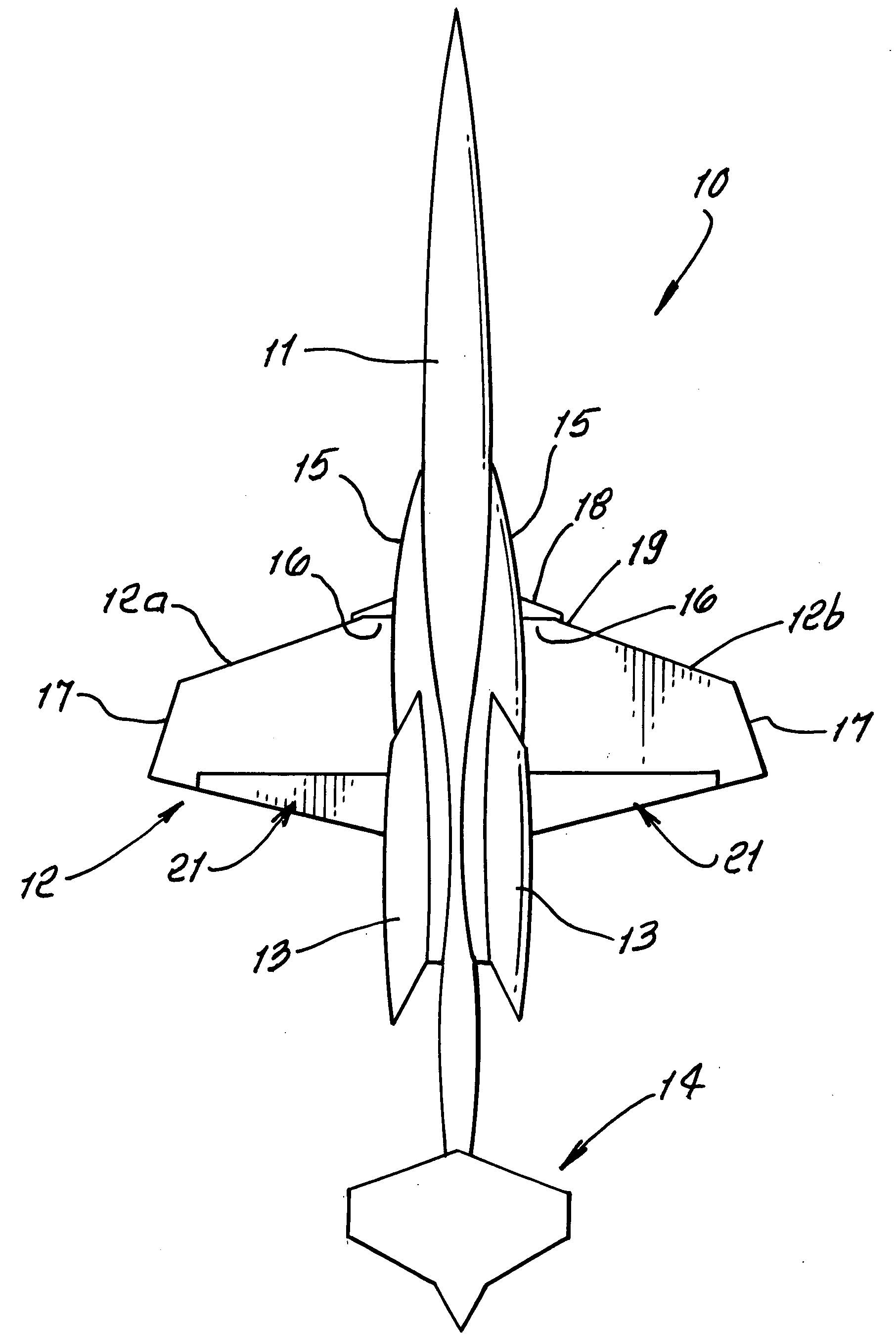
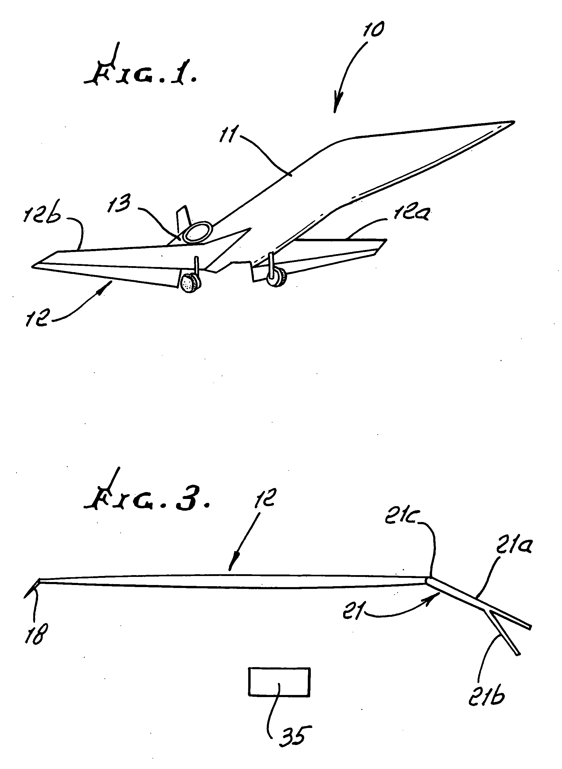
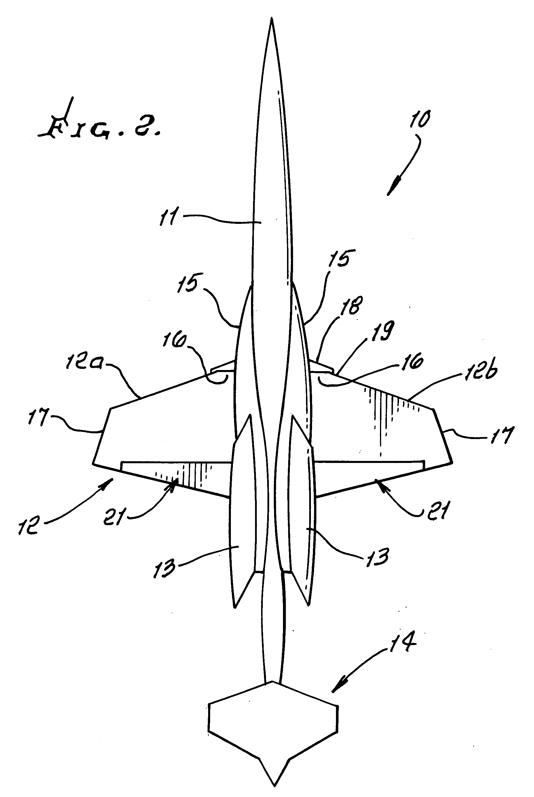
[0025]In the drawings, the preferred supersonic aircraft 10 has a fuselage 11, thin, laminar flow wing 12 including left and right wing sections 12a and 12b, jet engines 13 closely proximate opposite sides of the fuselage, and tail 14.

[0026]The strake is shown at 15, as a highly swept portion of the wing between the fuselage 11 and the inboard end 16 of the low sweep main wing panel. Other strake characteristics are referred to above.

[0027]The raked tip of each wing section is shown at 17, and has characteristics as referred to above.

[0028]Reversed fillet configuration, for each strake-fuselage junction leading edge, is indicated at 19, and has characteristics as referred to above.

[0029]The inboard leading edge flap is shown, for each wing section, at 18, and has characteristics as referred to above, and may have association with cavities in the fuselage or strake.

[0030]Hybrid plain-split flap, for each wing section, is provided at 21, and has characteristics as referred to above, a...


PUM


Abstract

Improved supersonic laminar flow wing structure, on a supersonic aircraft, having one or more of the following:
    • strake extending forwardly of the wing inboard extent,
    • raked wing tip,
    • reversed fillet at strake or fuselage junction,
    • inboard leading edge flap extending over less than about 15% of the inboard wing panel span,
    • hybrid plain-split flap having a lower surface portion deflectable downwardly relative to plain flap extent.

Description

[0001]This application claims priority from U.S. provisional application, Ser. No. 60 / 852,929, filed Oct. 18, 2006.BACKGROUND OF THE INVENTION[0002]This invention relates generally to efficient, supersonic, laminar flow aircraft wing configurations. More specifically it concerns improvements in the following configuration areas:[0003]a) strake,[0004]b) raked wing tip,[0005]c) reversed fillet wing-strake junction,[0006]d) inboard leading edge flap,[0007]e) hybrid plain-split flap.[0008]Certain prior Richard Tracy patents disclose a laminar flow wing for efficient supersonic flight (U.S. Pat. Nos. 5,322,242, 5,518,204, 5,897,076 and 6,149,101). Recent developments have led to five areas of improvement, principally benefiting low speed characteristics of aircraft using the wing. The wing described in the prior Tracy patents has a sharp, modified biconvex airfoil, with less than about 30 degrees leading edge sweep in order to maintain an attached shock at supersonic cruise conditions, a...

Claims


Application Information

Patent Timeline
IPC IPC(8): B64C21/00B64C23/06B64C3/50
CPCB64C3/10B64C7/00B64C9/18Y02T50/32B64C30/00Y02T50/12B64C9/24Y02T50/10Y02T50/30
Inventor CHASE, JAMES D.HENDERSON, MICHAELSTURDZA, PETER
Owner AERION INTPROP MANAGEMENT CORP
Why Eureka
Try Eureka