[0028]An
advantage of the present invention is the resulting lack of any need for rectification and low-pass
filtration of the analog measured signal, which is required in the prior art. This saves components and does away with the associated
sources of error. At the same time, “rectification” in the digital domain, that is, averaging and difference formation in the oversampled, bipolar digitized measured signal, which results in the above-described disadvantages, is also unnecessary. Rather, rectification occurs as a “natural” result of
digitization with a bipolar reference signal.
[0029]Particularly preferred embodiments of the present invention are defined in the dependent claims.
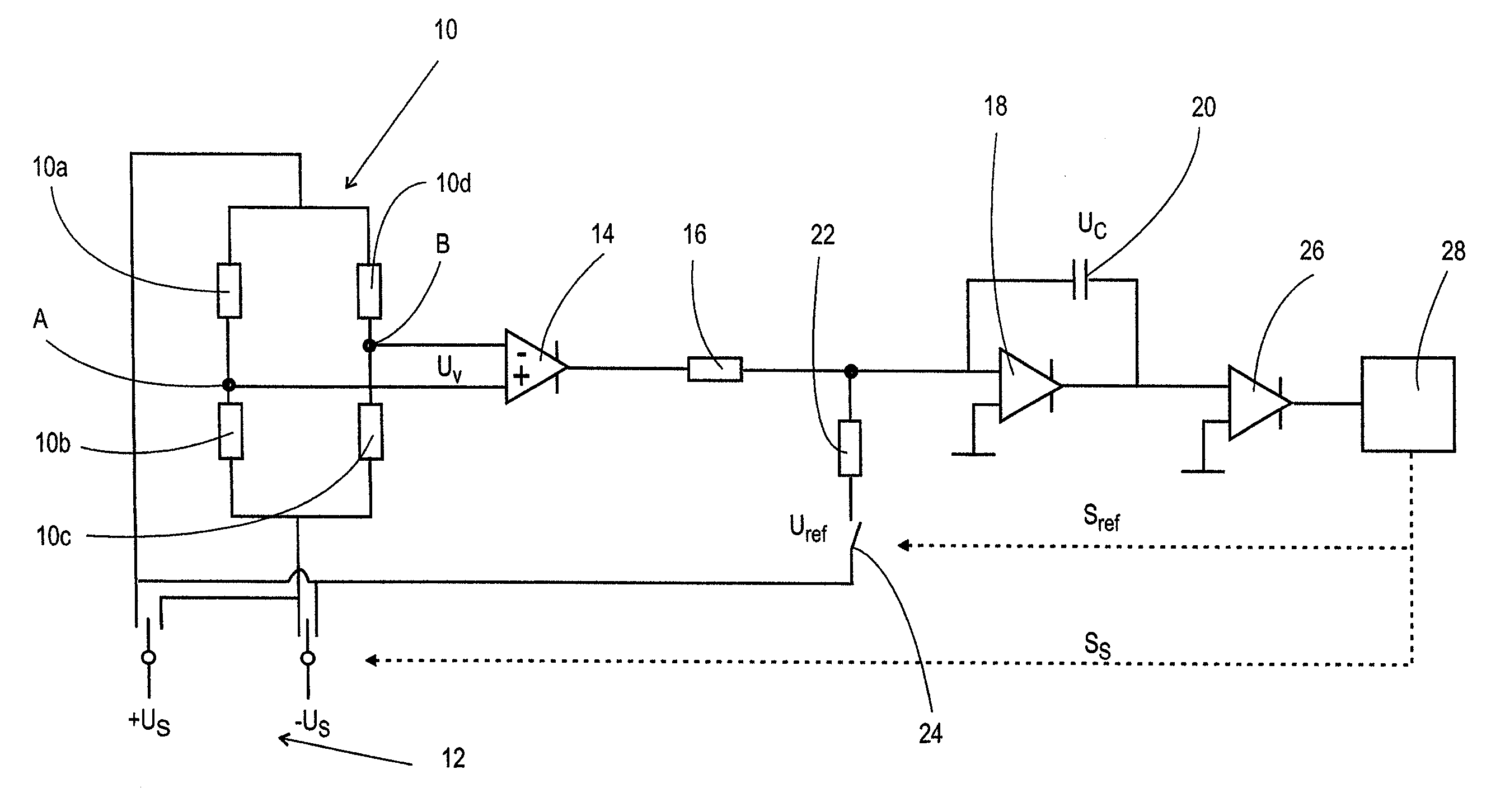
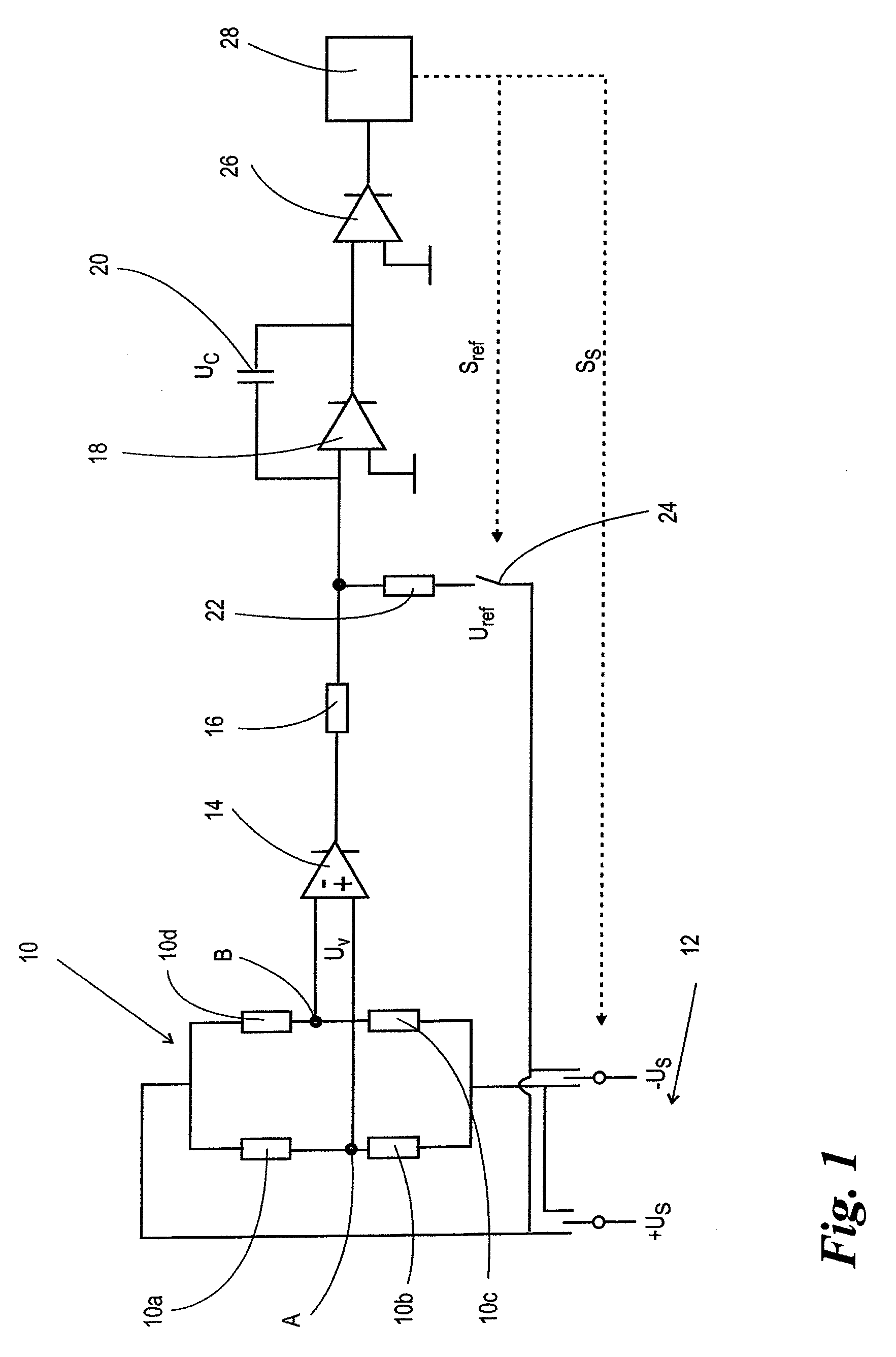
[0030]It is therefore advantageous if the switchable supply
voltage source serves together with an additional reference signal switch as a switchable reference
voltage source. This avoids the necessity of two voltage sources which must be matched to one another with additional synchronization means. Rather, the switchable supply
voltage source can be a bipolar source, the positive and negative connections of which can be connected to the measuring bridge alternately by means of a switch, the control of which depends on the
comparator output signal. The resulting bipolar rectangular signal can be fed, via a switch also controlled depending on the
comparator output signal, to the
integrator as a reference signal.
[0031]Advantageously, the dependence of the supply voltage and the reference
signal on the
comparator output signal is realized such that the comparator is configured to determine the time point of each crossing of the threshold value by the
integrator output signal, in particular the zero-crossing, and a controller is provided for feedback of the comparator output signal, the controller controlling the switchable supply voltage source, depending on the determined crossing time point, to cause a polarity reversal in the supply voltage, and the switchable reference voltage source to disconnect the working level of the reference signal from the integrator. In other words, it is preferably provided that, when the integrator output signal is compared with a threshold value, in particular the zero value, the time point at which the integrator output signal crosses the threshold value is detected and the polarity reversal of the supply voltage and the disconnection of the working level of the reference signal from the integrator are carried out depending on the detected time point. Typically, the control is configured so that threshold-crossing or zero-crossing of the integrator output signal, polarity reversal of the supply voltage and disconnection of the working level of the reference signal from the integrator input take place essentially simultaneously or synchronously with the
clock pulse of a clocked counter used for time measurement. However, targeted deviations from the synchronous
simultaneity can be set. Comparable deviations to improve the convergence behavior of a measurement amplification device are known from the above-cited DE 100 40 373 A1. The principles disclosed in that publication can easily be applied to the present invention.
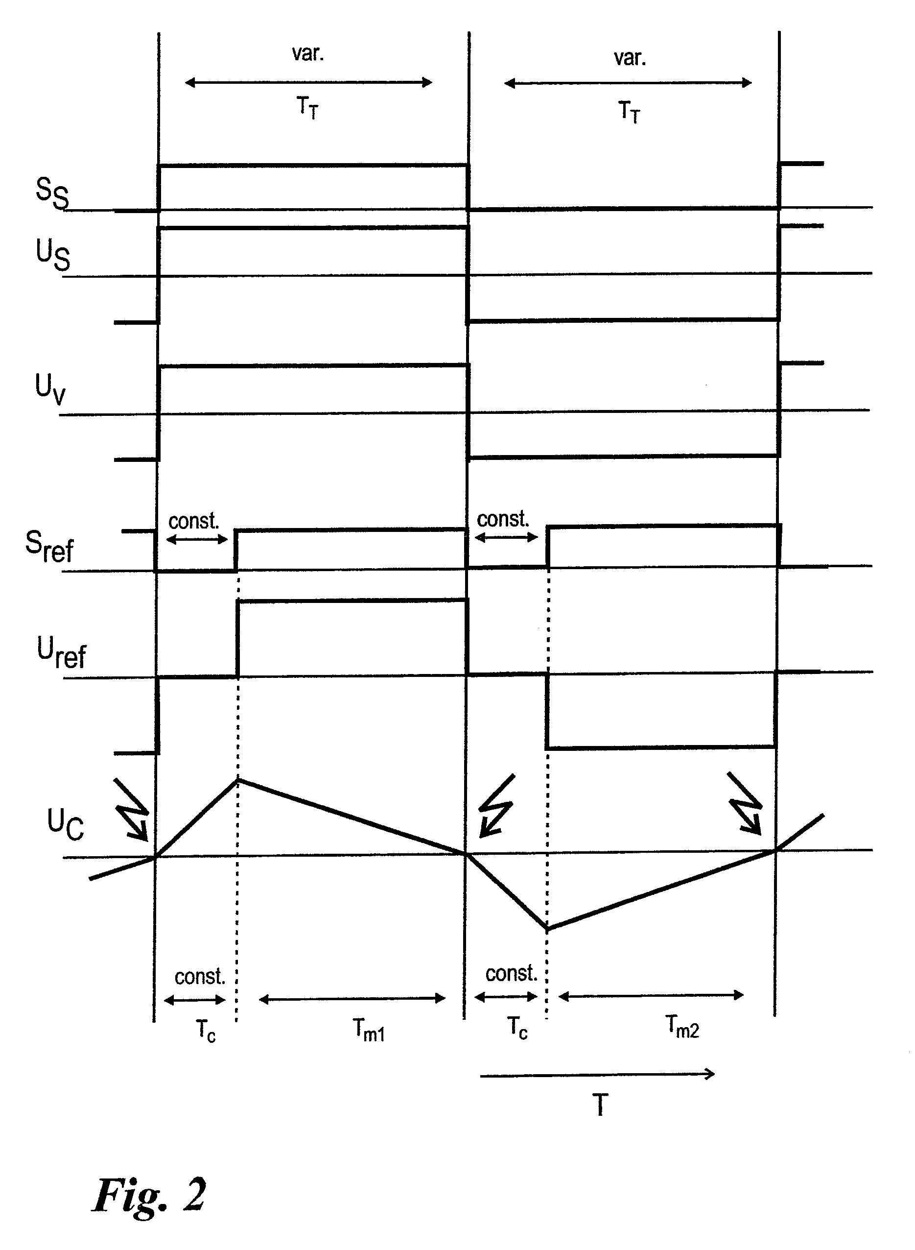
[0032]In a particularly advantageous development of this embodiment of the invention, it is provided that the controller is also configured to control the switchable reference voltage source following a pre-determined time interval after each disconnection of the working level of the reference signal from the integrator, for renewed application of the working level of the reference signal to the integrator. With regard to the inventive method, this means that the working level of the reference signal is applied to the integrator, in each case, after a pre-determined time interval following disconnection of the working level of the reference signal from the integrator. In other words, this means that the time during which the reference signal is not applied again or the rest level of the reference signal is applied to the integrator, and thus the time during which the
capacitor of the integrator is charged, is essentially fixed. The integrator is therefore given a pre-determined charging time. By contrast, the discharging time of the
capacitor, that is, the time during which the working level of the reference signal is applied, is variable and dependent on the quantity of integrated charge. This period, the measured interval, is ended by the comparator output signal and its duration is determined as a measure for the level of the measured
signal level. It should be noted that in this embodiment of the invention, in order to determine the measured interval, in practice the duration of the whole measuring
clock pulse, that is, the duration of an integration phase and a de-integration phase which, in a preferred embodiment of the invention is equal to the duration between two polarity changes in the supply voltage, can be used as a measure for the bridge detuning, since only one constant time interval, specifically the duration of the charging phase of the capacitor, is added to the variable
clock pulse portion, that is, the measured interval or the discharging phase of the capacitor.
[0033]Alternatively to the previously outlined variant with a variable measuring clock pulse, in another favorable embodiment of the invention, the measuring clock pulse can be kept constant. For this purpose, it is provided that the controller is also configured to control the switchable reference voltage source after a
fixed time interval following, in each case, a preceding application of the working level of the reference signal to the integrator, for renewed application of the working level of the reference signal to the integrator. With regard to the inventive method, this means that the working level of the reference signal is applied anew to the integrator, in each case, after a
fixed time interval following a preceding application of the reference signal to the integrator. In other words, the time period between two successive switching procedures for applying the working level of the reference signal to the integrator remains constant. However, the time period during which the working level of the reference signal remains applied to the integrator or the time during which the reference signal is not applied, or the rest level of the reference signal is applied, to the integrator is variable. The proportions of the charging and discharging phases within a fixed measuring clock pulse are therefore variable. It should be noted that, due to the simple dependency of the durations of the discharging phase and the charging phase on one another, in practice each of these phases is measured to determine the measured interval and can serve as the basis for a measure of the bridge detuning.

