
Method and apparatus for cooling in miniaturized electronics

a technology for electronics and miniaturized devices, applied in the direction of printed circuit aspects, electrical apparatus construction details, ultrasonic/sonic/infrasonic device construction, etc., can solve the problems of increasing heat not only to cause injury, but to exceed acceptable regulatory levels, and to reduce the effect of heat loss

Inactive Publication Date: 2009-08-20
GENERAL ELECTRIC CO
View PDF47 Cites 28 Cited by
  • Summary
  • Abstract
  • Description
  • Claims
  • Application Information

AI Technical Summary

Problems solved by technology

These higher temperatures can degrade the performance of the devices.
Moreover, the increased heat also emanates from the device.
Accordingly, in some applications, for example, in medical ultrasound imaging probes that contact individuals during an exam, the increased heat not only can cause injury, but may exceeded acceptable regulatory levels.
In the medical imaging area, and particularly, in the ultrasound imaging area, heat is often a serious problem as a result of the intense processing that has to be performed at the scan head of the ultrasound probe.
Additionally, increased heating of the scan head can affect the useful life of the ultrasound probe.
Current methods to dissipate the heat in devices with miniaturized electronics typically include heat sinks or heat exchangers that are complex, large and heavy.
These current heat dissipation methods also add time and cost to manufacturing and maintenance, as well as result in a device that is often more cumbersome to use.
As a result of having to use the housing with channels, the overall device size and weight is increased, which affects the portability and potential applications for the ultrasound system.
Also, the device is often time consuming to manufacture because the manufacturing steps have to be performed by hand.

Method used


Image

  • Method and apparatus for cooling in miniaturized electronics
  • Method and apparatus for cooling in miniaturized electronics
  • Method and apparatus for cooling in miniaturized electronics

Examples


Embodiment Construction

[0018]The foregoing summary, as well as the following detailed description of certain embodiments of the present invention, will be better understood when read in conjunction with the appended drawings. To the extent that the figures illustrate diagrams of the functional blocks of various embodiments, the functional blocks are not necessarily indicative of the division between hardware circuitry. Thus, for example, one or more of the functional blocks (e.g., processors or memories) may be implemented in a single piece of hardware (e.g., a general purpose signal processor or random access memory, hard disk, or the like). Similarly, the programs may be stand alone programs, may be incorporated as subroutines in an operating system, may be functions in an installed software package, and the like. It should be understood that the various embodiments are not limited to the arrangements and instrumentality shown in the drawings.

[0019]As used herein, an element or step recited in the singu...


PUM


Abstract

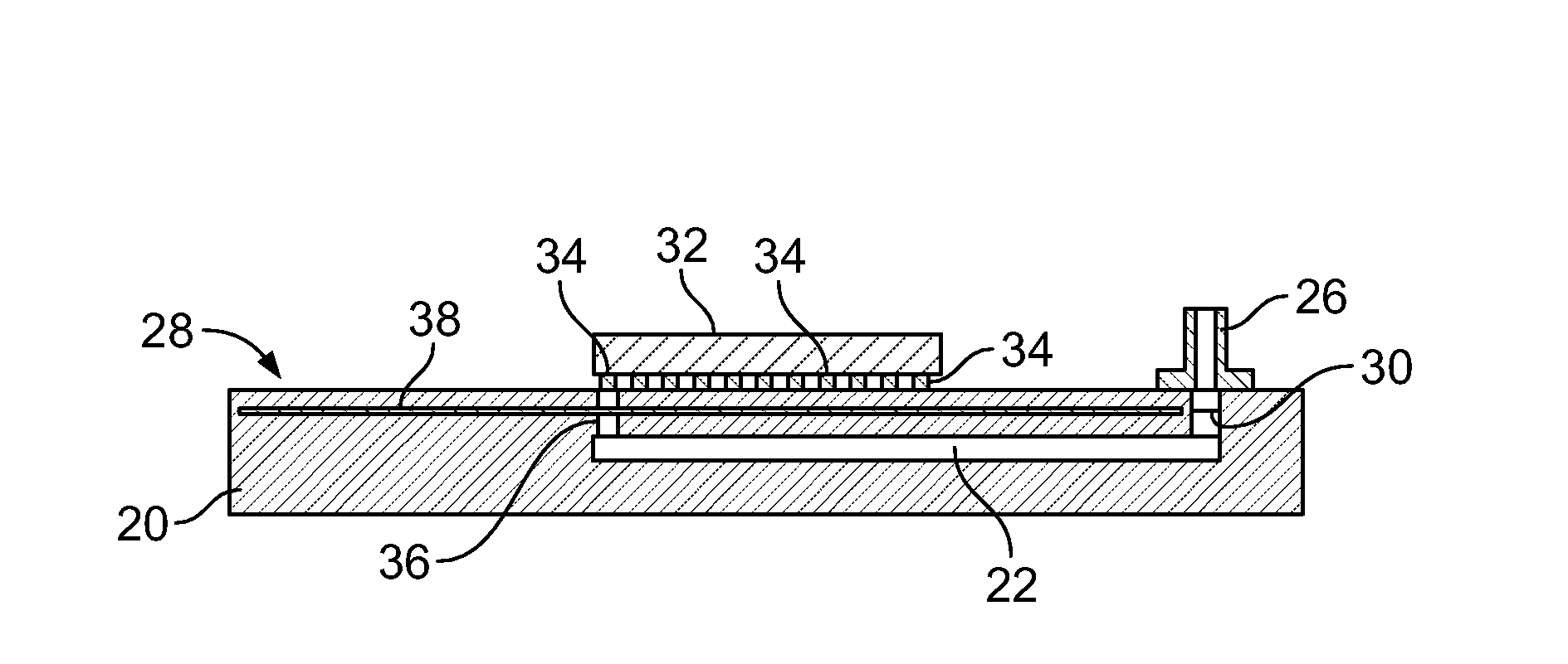
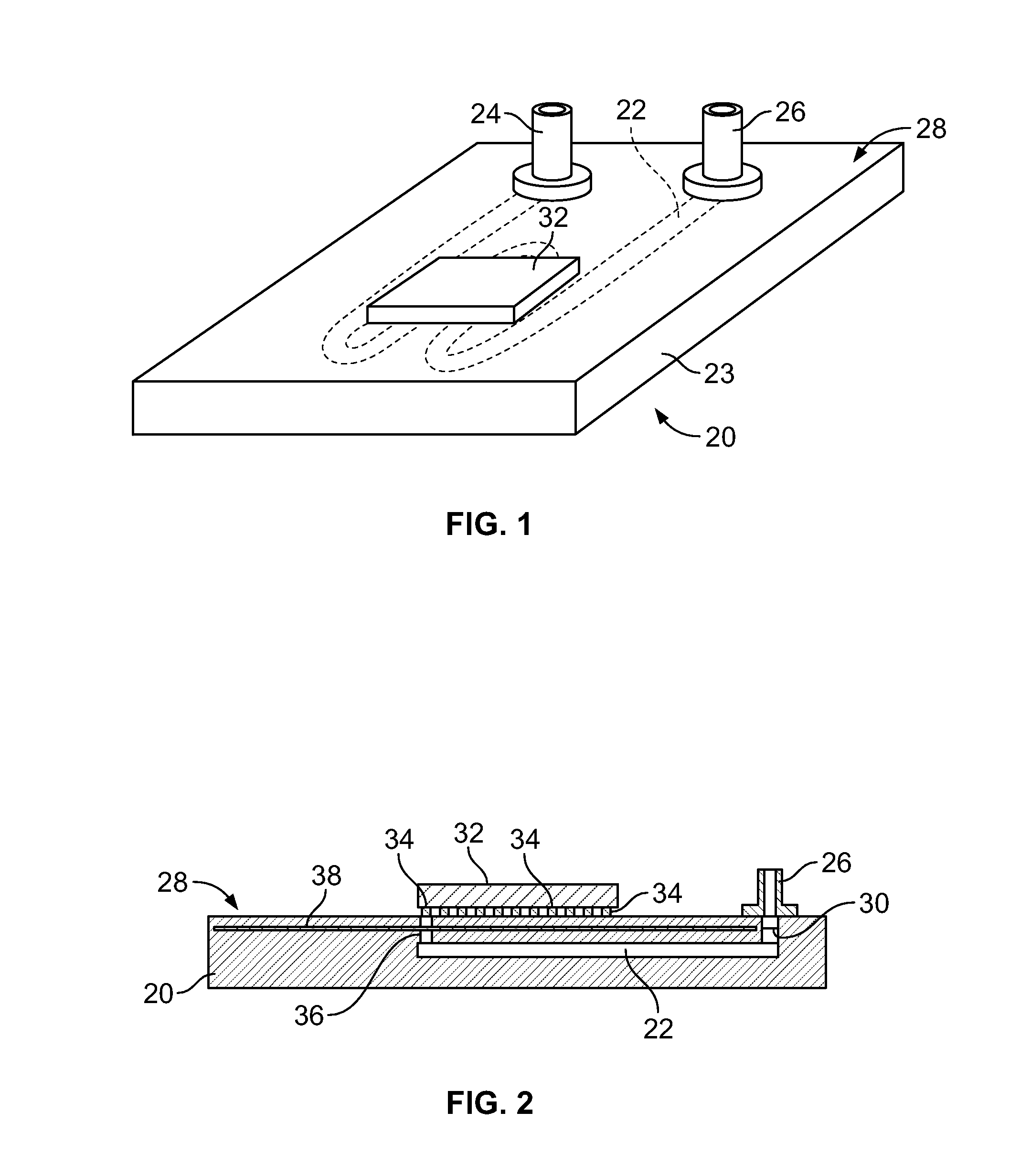
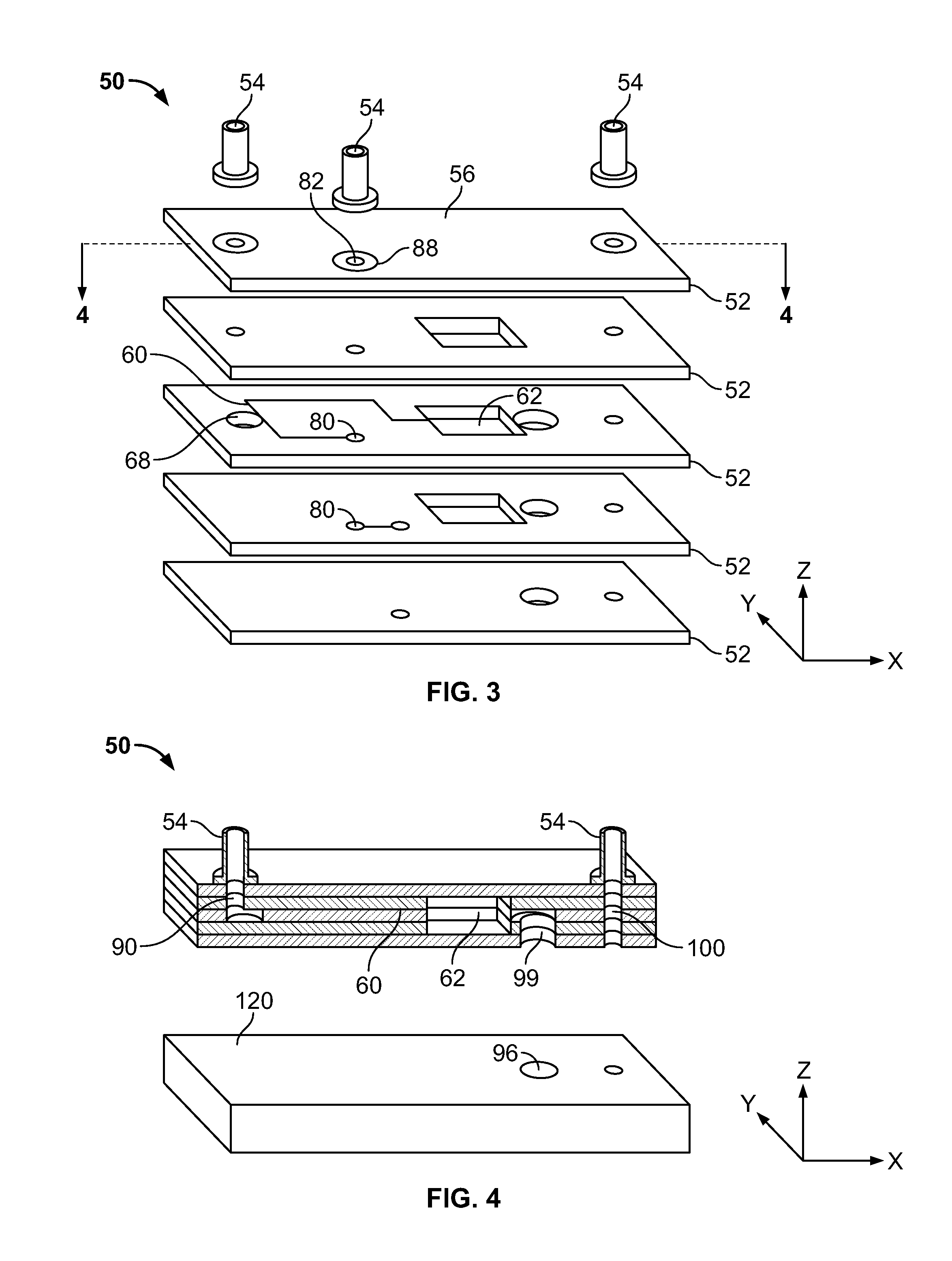
A method and apparatus for cooling in miniaturized electronics are provided including in an electronic circuit board. The electronic circuit includes a substrate and at least one integrated channel within the substrate configured to allow fluid flow therethrough.

Description

BACKGROUND OF THE INVENTION[0001]One or more embodiments of this invention relate generally to a method and apparatus for cooling miniaturized electronics, and more particularly, to electronic circuit boards having integrated cooling channels.[0002]As electronic devices are miniaturized, the amount of heat generated by the more densely populated electronics increases. As the amount of generated heat increases, the components within the device also operate at higher temperatures. These higher temperatures can degrade the performance of the devices. Moreover, the increased heat also emanates from the device. Accordingly, in some applications, for example, in medical ultrasound imaging probes that contact individuals during an exam, the increased heat not only can cause injury, but may exceeded acceptable regulatory levels. Accordingly, these devices have to be cooled.[0003]In the medical imaging area, and particularly, in the ultrasound imaging area, heat is often a serious problem as...

Claims


Application Information

Patent Timeline
IPC IPC(8): H05K7/20
CPCH01L23/473H01L2924/09701H05K1/0272H05K1/0306H05K3/4611H05K3/4629H01L2924/0002H05K3/4697H05K2201/064H01L2924/00A61B8/44
Inventor HAVERI, HEIKKI ANTTI MIKAEL
Owner GENERAL ELECTRIC CO
Learn More