
Picture processing apparatus, picture processing method, picture processing method program and picture processing method program recording medium

a picture processing apparatus and picture processing method technology, applied in the field of picture processing apparatus, picture processing method program and picture processing method program recording medium, can solve the problems of high-frequency components lost in the quantization process, prediction error also increases, and the effect of removing block noise, simple configuration and high degree of reliability

Inactive Publication Date: 2009-08-20
SONY CORP
View PDF4 Cites 111 Cited by
  • Summary
  • Abstract
  • Description
  • Claims
  • Application Information

AI Technical Summary

Benefits of technology

[0018]Addressing the problems described above, the embodiments of the present invention present a picture processing apparatus capable of repressing block noises with a high degree of reliability so as to effectively prevent the picture quality of the video signal SV from deteriorating by making use of a configuration simpler than the existing picture processing apparatus and presents a picture processing method to be adopted by the picture processing apparatus, a picture processing method program implementing the picture processing method as well as a recording medium used for storing the picture processing method program.
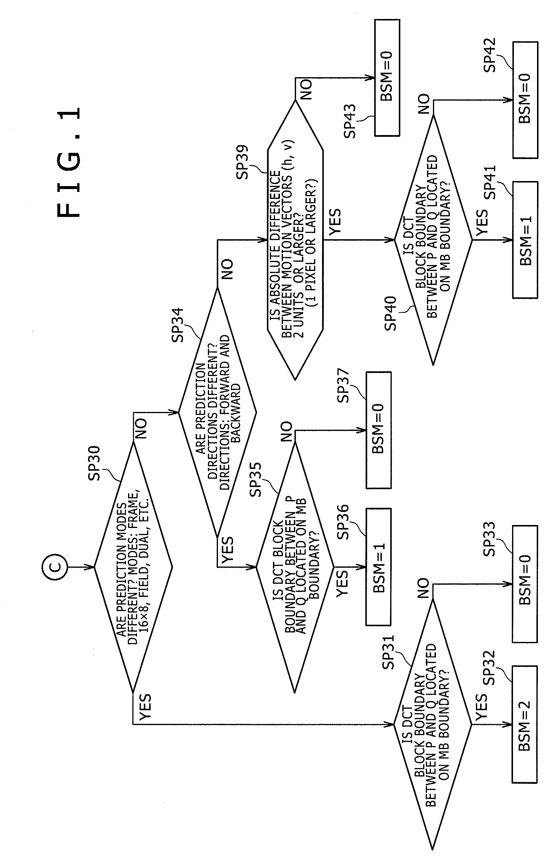
[0032]In the configurations according to the second, fifth, eighth and eleventh modes of the present invention, processing is carried out to code picture data by selecting the setting of picture types from a frame structure of the picture data and from a field structure of the picture data in order to generate a bit stream. Thus, processing can be carried out to code picture data to produce a bit stream by adoption of a coding method such as the MPEG-2 coding / decoding method which is implemented by selecting the setting of picture types from a frame structure of the picture data and from a field structure of the picture data. In addition, a deblocking filter in is used in the processing carried out to code the picture data in order to carry out a filtering process of removing block noises from the picture data on the basis of filtering-location identifying information, boundary-strength determination information and a quantization parameter. Thus, typically, an H.264 / AVC deblocking filter can be used to for carrying out the filtering process remove block noises from the picture data, which has been obtained as a result of a decoding process included in the processing carried out to code the picture data, on the basis of the filtering-location identifying information, the boundary-strength determination information and the quantization parameter. As a result, in comparison with the existing technology, a technology according to the embodiments of the present invention is capable of removing block noises by dynamically changing the strength of the filtering process in a simple configuration. That is to say, in comparison with the existing technology, the technology according to the embodiments of the present invention is capable of removing block noises with a high degree of reliability and, hence, effectively avoiding deteriorations of the quality of a picture by making use of a simple configuration. On top of that, if prediction modes for generating the predicted values in adjacent orthogonal transform process units are different from each other, the control step is carried out to set the boundary-strength determination information so that the strength of the filtering process becomes large in comparison with a case in which the adjacent predicted-value generation units have the same prediction mode. Thus, the strength of the filtering process can be controlled to properly match the prediction mode peculiar to the bit stream which has been generated in processing executed to code the picture data by selecting the setting of picture types from a frame structure of the picture data and from a field structure of the picture data. As a result, the embodiments of the present invention are capable of removing block noises with an even higher degree of reliability and, hence, effectively avoiding deteriorations of the quality of a picture.
[0034]A picture processing apparatus configured in accordance with the embodiments of the present invention is capable of repressing block noises with a high degree of reliability so as to effectively prevent the picture quality of the video signal SV from deteriorating by making use of a configuration simpler than the existing picture processing apparatus.

Problems solved by technology

In addition, the MPEG-2 coding apparatus delimits the rearranged pictures into macroblock units, each of which is used as the predicted-value generation unit cited above, and generates a prediction error, which is a difference between the true value of a macroblock unit and a predicted value according to the type of the picture, for each of the macroblock units.
In the coding processing adopting the MPEG-2 or H.264 / AVC coding / decoding method, if the data compression rate is increased, high-frequency components are lost in the quantization process.
In addition, in the case of a vigorous motion or the like, the prediction error also increases.
As a result, high-frequency components are also lost as well in the quantization process and, thus, gradation differences are generated on boundaries between DCT blocks of the video signal SV obtained as a result of the decoding processing.
On top of that, in the case of a vigorous motion, the prediction error in the macroblock also increases and, as a result, gradation differences are generated on boundaries between macroblocks.
The gradation differences generated on the boundaries between DCT blocks and on the boundaries between macroblocks due to lost high-frequency components substantially deteriorate the quality of the picture.
In the case of the MPEG-2 coding / decoding method, however, the use of a deblocking filter is not prescribed.
It is thus necessary to detect merely block-noise components from a base-band video signal with a high degree of reliability so that, in consequence, there is raised a problem of a complicated overall configuration.
Because of existence of various processes not described by the H.264 / AVC specifications as processed for the MPEG-2 coding / decoding method, however, the technique disclosed in Japanese Patent Laid-Open No. 2007-36463 raises a problem of inadequacies still existing in the practical use.

Method used


Image

  • Picture processing apparatus, picture processing method, picture processing method program and picture processing method program recording medium
  • Picture processing apparatus, picture processing method, picture processing method program and picture processing method program recording medium
  • Picture processing apparatus, picture processing method, picture processing method program and picture processing method program recording medium

Examples


first embodiment

[0060](1) Constitution of the Embodiment

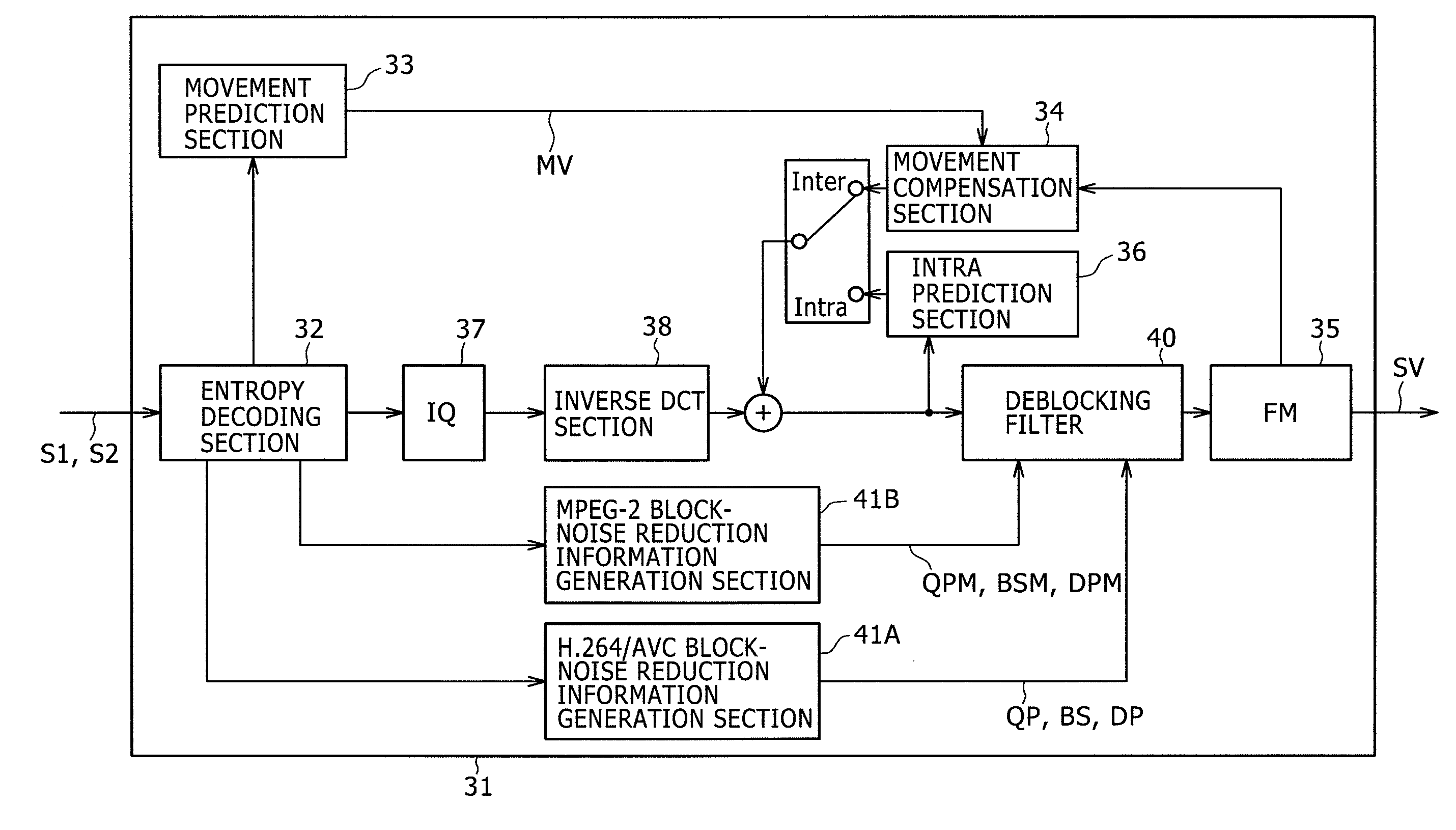
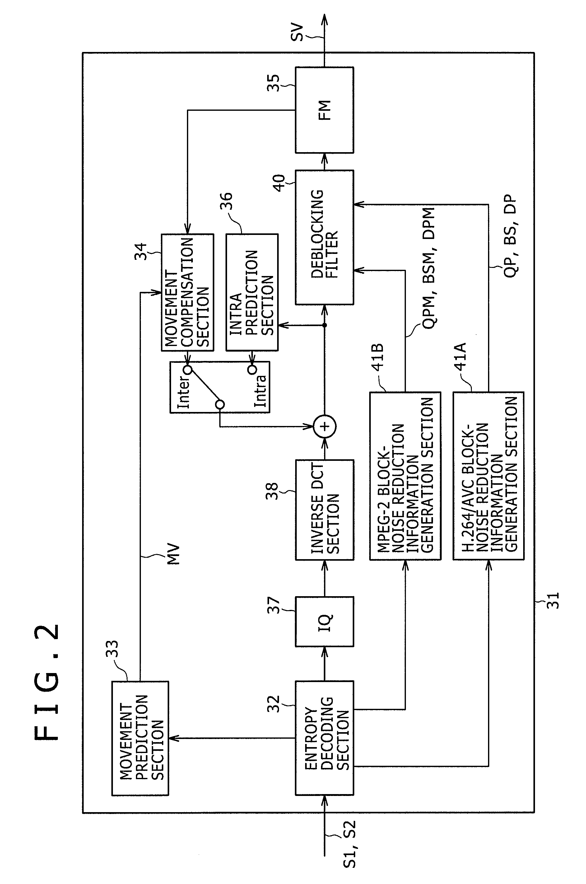
[0061]FIG. 2 is a block diagram showing the configuration of a decoding apparatus 31 according to a first embodiment of the present invention. The decoding apparatus 31 is a decoding apparatus capable of decoding both an MPEG-2 bit stream S1 and an H.264 / AVC bit stream S2. The decoding apparatus 31 is provided with a controller for switching the components of the decoding apparatus 31 from operations for processing the MPEG-2 bit stream S1 to operations for processing the H.264 / AVC bit stream S2 and vice versa so as to enable the decoding apparatus 31 to decode an MPEG-2 bit stream S1 or an H.264 / AVC bit stream S2. The controller itself is not shown in the figure though.

[0062]In the decoding apparatus 31, an entropy decoding section 32 carries out an entropy decoding process as a part of the decoding processing, which is being carried out by the decoding apparatus 31, on an MPEG-2 bit stream S1 or an H.264 / AVC bit stream S2 by properly switchi...

second embodiment

[0201]It is to be noted that, in the case of the first embodiment explained so far, a filtering process can also be carried out for a vertical-direction inter-center-line gap between DCT block boundaries. However, the scope of the embodiments of the present invention is by no means limited to the first embodiment. For example, the difference in DCT type can also be taken into consideration in order to carry out the filtering process more finely. That is to say, in the case of a field structure shown in the diagram of FIGS. 19A and 19B, a DCT block noise Q to be removed and a DCT block noise P adjacent to the DCT block noise Q may exist in the same macroblock MB. Even in this case, the two block noises, i.e., the DCT block noise Q and the DCT block noise P, are generated as noises of blocks created from a top field and a bottom field which are different from each other from the time point of view. In this case, the relevance and resemblance of the two block noises, i.e., the DCT bloc...

third embodiment

[0202]FIG. 20 is a block diagram showing a coding apparatus 51 according to a third embodiment of the present invention. The coding apparatus 51 is a coding apparatus capable of generating both an MPEG-2 bit stream S1 and an H.264 / AVC bit stream S2. The coding apparatus 51 is provided with a controller for switching the components employed in the coding apparatus 51 from coding operations for the MPEG-2 bit stream S1 to coding operations for the H.264 / AVC bit stream S2 and vice versa so as to enable the coding apparatus 51 to generate an MPEG-2 bit stream S1 or an H.264 / AVC bit stream S2. The controller itself is not shown in the figure though. It is to be noted that components employed in the coding apparatus 51 shown in the block diagram of FIG. 20 as components identical with their respective counterparts employed in the decoding apparatus 31 shown in the block diagram of FIG. 2 are denoted by the same reference numerals as the counterparts and the explanation of the identical co...


PUM


Abstract

Disclosed herein is a picture processing apparatus for carrying out decoding processing to produce picture data from a bit stream generated previously in processing performed typically by a coding apparatus to code the picture data by selection of setting of picture types from a frame structure of the picture data and from a field structure of the picture data and by execution of an orthogonal transform process for each orthogonal transform process unit of the picture data on a prediction error, which is a difference between a predicted value generated for each predicted-value generation unit of the picture data and the true value of the picture data.

Description

CROSS REFERENCES TO RELATED APPLICATIONS[0001]The present invention contains subject matter related to Japanese Patent Application JP 2008-032893 filed in the Japan Patent Office on Feb. 14, 2008, the entire contents of which being incorporated herein by reference.BACKGROUND OF THE INVENTION[0002]1. Field of the Invention[0003]The present invention relates to a picture processing apparatus, a picture processing method adopted by the picture processing apparatus, a picture processing method program implementing the picture processing method and a recording medium used for recording the picture processing method program. For example, the embodiments of the present invention can be applied to a stream decoding apparatus capable of decoding an MPEG (Moving Picture Experts Group)-2 bit stream and an MPEG-4 Part10 AVC (Advanced Video Coding) bit stream which is referred to as an H.264 / AVC bit stream in the following description. In comparison with the existing technology, a technology acc...

Claims


Application Information

Patent Timeline
IPC IPC(8): H04N7/26H04N19/117H04N19/50H04N19/134H04N19/159H04N19/167H04N19/176H04N19/182H04N19/196H04N19/44H04N19/503H04N19/593H04N19/60H04N19/61H04N19/625H04N19/86H04N19/91
CPCH04N19/139H04N19/159H04N19/176H04N19/61H04N19/117H04N19/86H04N19/16H04N19/18H04N19/182H04N19/82H04N19/14
Inventor MINAMOTO, JUNICHI
Owner SONY CORP
Learn More