
Optical Device for Measuring a Physical Parameter in a Hydrogen Contaminated Sensing Zone

a technology of optical sensors and physical parameters, applied in the direction of amplifiers, transmissions, electrical devices, etc., can solve the problems of optical sensors being susceptible to contamination, optical sensors

Active Publication Date: 2009-08-20
WEATHERFORD CANADA
View PDF26 Cites 37 Cited by
  • Summary
  • Abstract
  • Description
  • Claims
  • Application Information

AI Technical Summary

Benefits of technology

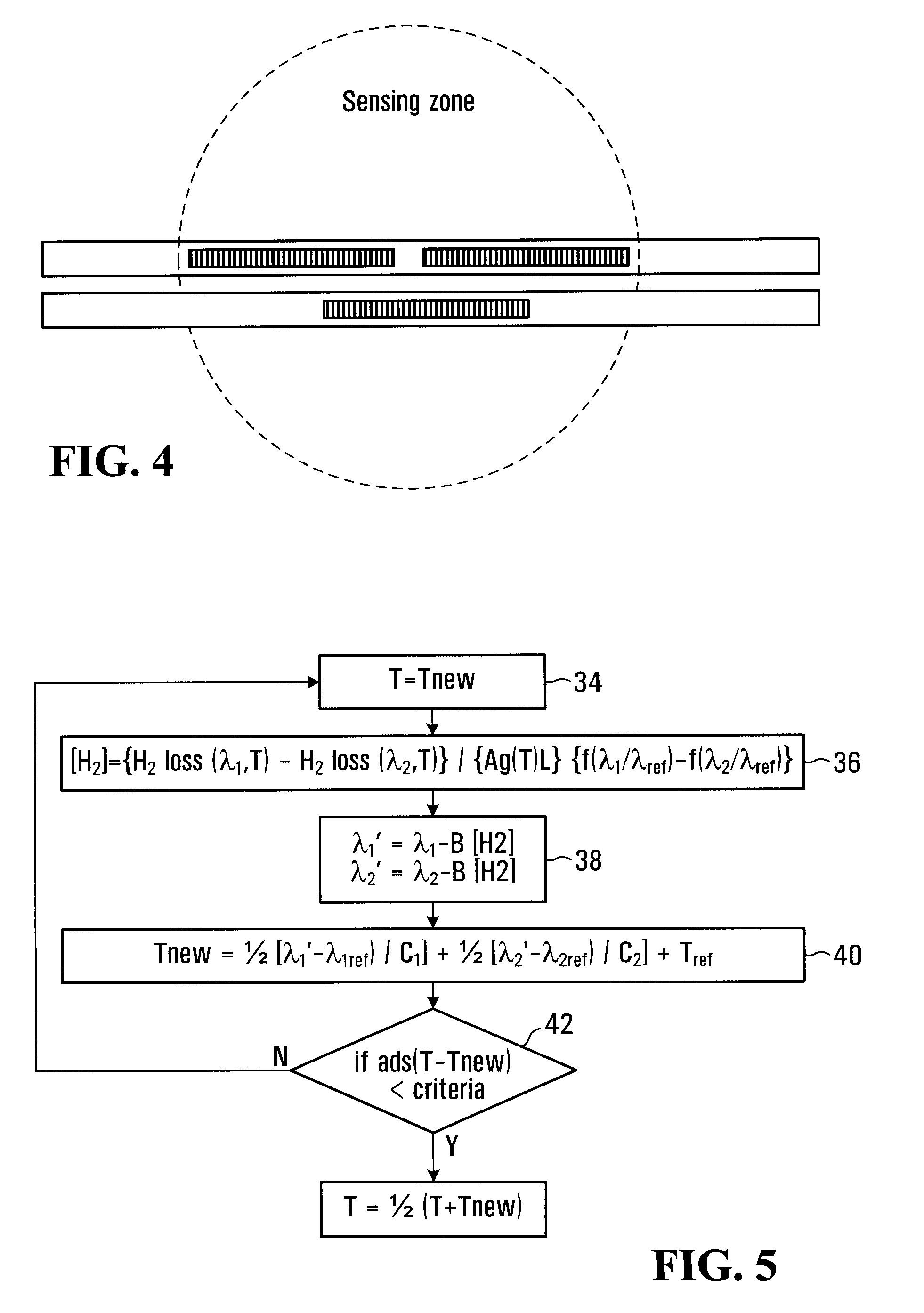
The invention provides a signal processing apparatus that can measure the concentration of hydrogen in an optical sensor, which is placed in a sensing zone that contains hydrogen and is susceptible to contamination by hydrogen. The apparatus uses a processing entity to process the response of the optical sensor to an optical excitation and derives information on the hydrogen concentration in the optical sensor. The invention also provides a method for measuring temperature in a well of an oil extraction installation, which contains hydrogen susceptible to migrate into the optical sensor. The optical sensor has first and second optical components and a common optical path containing the first and second optical components. The first and second optical components are capable of generating an optical response to an optical excitation and the temperature measurement is corrected for effects of hydrogen migration into the optical sensor.

Problems solved by technology

The optical sensor is susceptible to contamination by hydrogen potentially present in the vicinity of the optical sensor.
The optical sensor is susceptible to contamination by hydrogen potentially present in the sensing zone which alters the response manifested by the optical components to the physical parameter.

Method used


Image

  • Optical Device for Measuring a Physical Parameter in a Hydrogen Contaminated Sensing Zone
  • Optical Device for Measuring a Physical Parameter in a Hydrogen Contaminated Sensing Zone
  • Optical Device for Measuring a Physical Parameter in a Hydrogen Contaminated Sensing Zone

Examples


Embodiment Construction

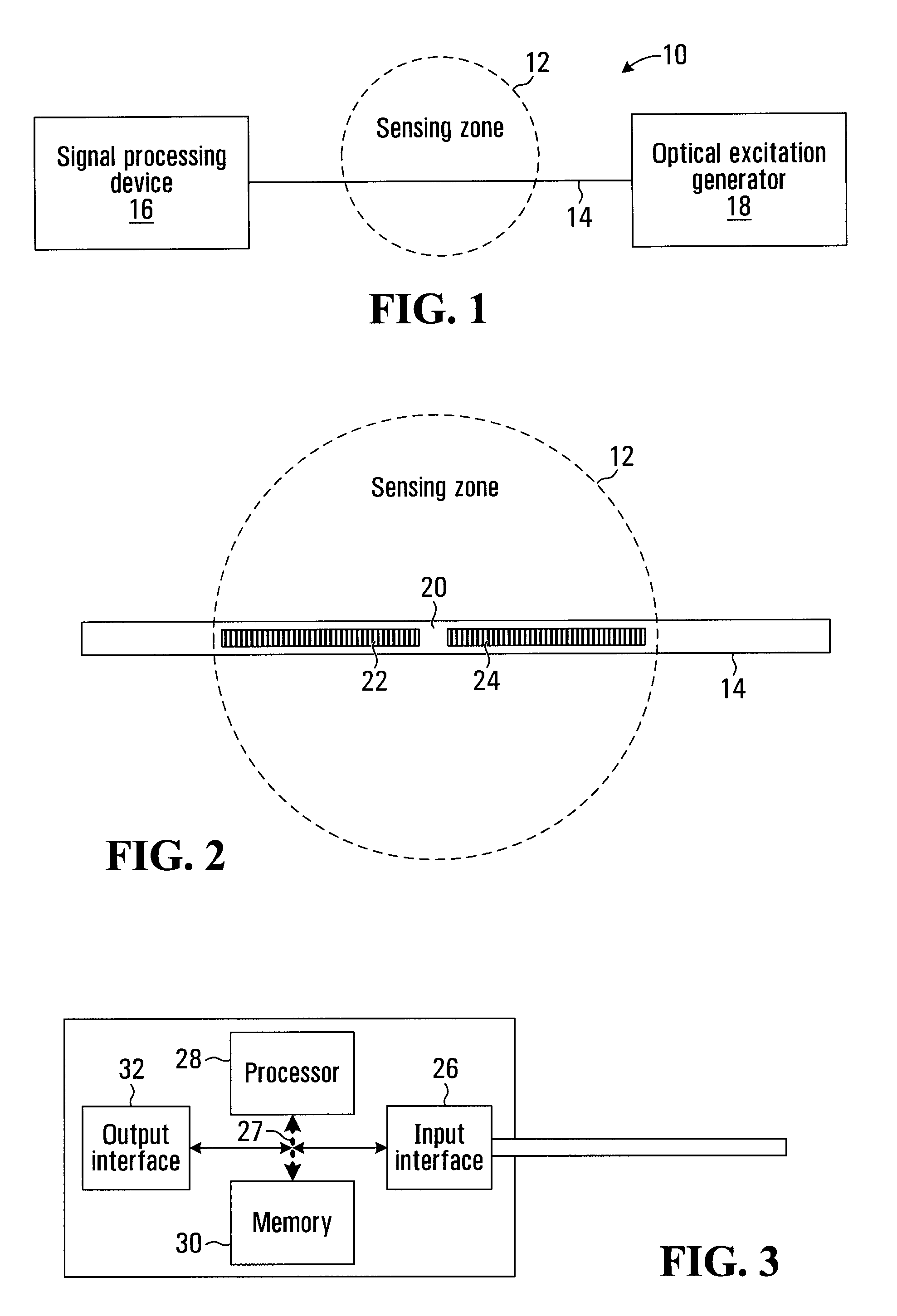
[0026]FIG. 1 shows a measurement apparatus 10 that measures the intensity of a physical parameter, such as temperature, pressure of strain. The measurement is performed in a sensing zone 12. Generally, the measurement apparatus 10 has an optical sensor 14 which is located in the sensing zone 12, a signal processing device 16 which performs an analysis of the optical response generated by the optical sensor 14, and an optical excitation generator 18 that injects into the optical sensor 14 an optical excitation.

[0027]The sensing zone 12 is the area where the measurement is to be made. In this specific example of implementation, the sensing zone 12 is susceptible to contain gaseous hydrogen. The hydrogen can migrate into the optical sensor and affect the way the sensor responds to the physical parameter. This will, in turn, produce an erroneous reading of the intensity of the physical parameter at the signal processing device 16 unless the measurement is corrected to take into account ...


PUM

PropertyMeasurementUnit
concentrationaaaaaaaaaa
optical excitationaaaaaaaaaa
lengthaaaaaaaaaa

Abstract

A signal processing apparatus which has an input for receiving a signal conveying a response from first and second optical components to an optical excitation. The first and second optical components are in an optical sensor which is intended to be placed in a sensing zone. The sensing zone contains hydrogen susceptible to migrate into the optical sensor. The signal processing apparatus has a processing entity for processing the response from the first and second optical components to derive information on hydrogen concentration in the optical sensor.

Description

CROSS-REFERENCE TO RELATED APPLICATION[0001]The present application claims the benefit under 35 USC §119(e) of prior U.S. provisional patent application Ser. No. 60 / 825,019 filed on Sep. 8, 2006, hereby incorporated by reference herein.FIELD OF THE INVENTION[0002]The invention relates to optical measuring devices and in particular to a measuring device, components thereof and methods for measurement for applications where the sensing zone in which the measurement is to be made contains hydrogen that can potentially contaminate optical components of the optical measuring device.BACKGROUND OF THE INVENTION[0003]The effects of hydrogen diffusion into optical fibers have been studied for more than a decade. Four principal aspects have been the objects of these studies: enhancing the photosensitivity of optical fibers, Bragg wavelength shift due to an increase of the effective index of optical fiber, absorption losses increase and hydrogen sensing.More specifically, the presence of hydro...

Claims


Application Information

Patent Timeline
Patent Type & Authority Applications(United States)
IPC IPC(8): G06F19/00G02B6/00G06F15/00G01K1/00
CPCE21B47/065G01N21/774G01D5/35303E21B47/07G01D5/35316E21B47/06
Inventor VINCELETTE, ANDRELEFEBVRE, PAULNADEAU, JEAN-FRANCOIS
Owner WEATHERFORD CANADA
Learn More