Eureka AIR delivers breakthrough ideas for toughest innovation challenges, trusted by R&D personnel around the world.

Polymer melt extrusion which has potential use in die design

a technology of polymer melt and extrusion, which is applied in the field of polymer melt extrusion, can solve the problems of frequent remeshing, low extrusion rate, and inability to provide a reliable method for die swell calculation, etc., and achieves simple and reliable calculation, high extrusion rate, and accurate transient swell calculation

Active Publication Date: 2009-08-20
TATA CONSULTANCY SERVICES LTD
View PDF17 Cites 8 Cited by
  • Summary
  • Abstract
  • Description
  • Claims
  • Application Information

AI Technical Summary

Benefits of technology

[0045]It is another object of the present invention to accurately calculate the die swell which is needed for die designing applications.
[0047]It is still another object of the present invention to provide a simple and convenient method to solve the complex viscoelastic constitutive equations for die swell calculations.
[0051]Yet another object of the present invention is to provide a system wherein said system calculates the die swell for high extrusion rate and to solve the complex viscoelastic equations for the polymer melt along with the flow kinematics in an effective manner.
[0052]One more object of the present invention is to accurately calculate the die swell transiently.
[0053]Again another object of the present invention is to provide a simple and reliable system to accurately calculate the die swell considering the die geometry, and polymer melt characteristics.SUMMARY OF THE INVENTION
[0058]a mesh corrector means adapted to analyze the die swell obtained from said simulator and to correct motion of the computational mesh and polymer melt to simulate the die swell accurately;

Problems solved by technology

This is a challenging task due to the requirement for simulation of the free surface which needs special techniques in the traditionally used Eulerian framework.
But there were problems associated with mesh distortion and frequent remeshing was required.
The method disclosed in this patent does not provide a reliable method to calculate the die swell.
The drawback of the disclosed method is that any real-time dynamic die swell correction is not possible.
A drawback of the disclosed method is that the analogy is not strong enough to give accurate die swell predictions for all polymer materials and flow rate as the disclosed method can only be used for low Reynolds number pressure driven fluid flow.

Method used


Image

  • Polymer melt extrusion which has potential use in die design
  • Polymer melt extrusion which has potential use in die design
  • Polymer melt extrusion which has potential use in die design

Examples


example 1

Die Swell Analysis of LLDPE Melt for a Long Capillary Die

[0135]Die swell analysis using the present invention through a capillary die of length to diameter ratio, L / D=19.2 were compared with the experiments and predictions of Guillet et al. [as published in: Piau J. M., Agassant J. F. (Eds.) Rheology for Polymer Melt Processing, Elsevier, 1996, p. 285] and Be'raudo et al. While the constitutive model and the values of its parameters were identical to that used by Guillet et al. and Be'raudo et al., the simulation technique (ALE) was different than that used by these authors. Therefore the results provided a direct way of comparing performance of the two types of simulation techniques. The results are shown in FIG. 5, FIG. 6 and FIG. 7 for three different shear rates. ALE based calculations of die swell profile were in good agreement with the experiments at all shear rates.

example 2

Die Swell Analysis for a of LLDPE Melt Short Die with an Upstream Axisymmetric Contraction-Large Memory

[0136]The calculations based on the present invention were compared with the experiments of Guillet et al. and simulations of Be'raudo et al. for extrusion of LLDPE from a short capillary die having length to diameter ratio (L / D)=4.8 and D=0.65 mm. In this simulation the entire die geometry including the converging section of the die was considered. The simulation results shown in FIG. 8 were compared better with experiments than those of Be'raudo et al.

example 3

Die Swell of HDPE from a Planar Die

[0137]ALE based die swell results of simulations were compared with the simulations results and experiments of Ahmed et al. [as published in ‘The experimental observation and numerical prediction of planar entry flow and die swell for molten polyethylenes, J. Non-Newtonian Fluid Mech. 59 (1995) 129-153’] for Natene grade HDPE through a planar contraction. The die dimensions used in the simulations were the same as those reported by Ahmed et al. For the simulations using the present invention, the exponential PTT constitutive model was used, while Ahmed et al. used the KBKZ model with Wagner damping parameter, k=0.35. The PTT model parameter, ε was estimated to be 0.27. The swell ratio i.e., the thickness of the extrudate to the slit thickness at die exit was computed at a distance of 2 mm from the die exit. The results are shown in Table 1. The analysis of swell using the present invention had shown a better match with the experimental data.

TABLE 1...


PUM

PropertyMeasurementUnit
Fractionaaaaaaaaaa
Fractionaaaaaaaaaa
Fractionaaaaaaaaaa

Abstract

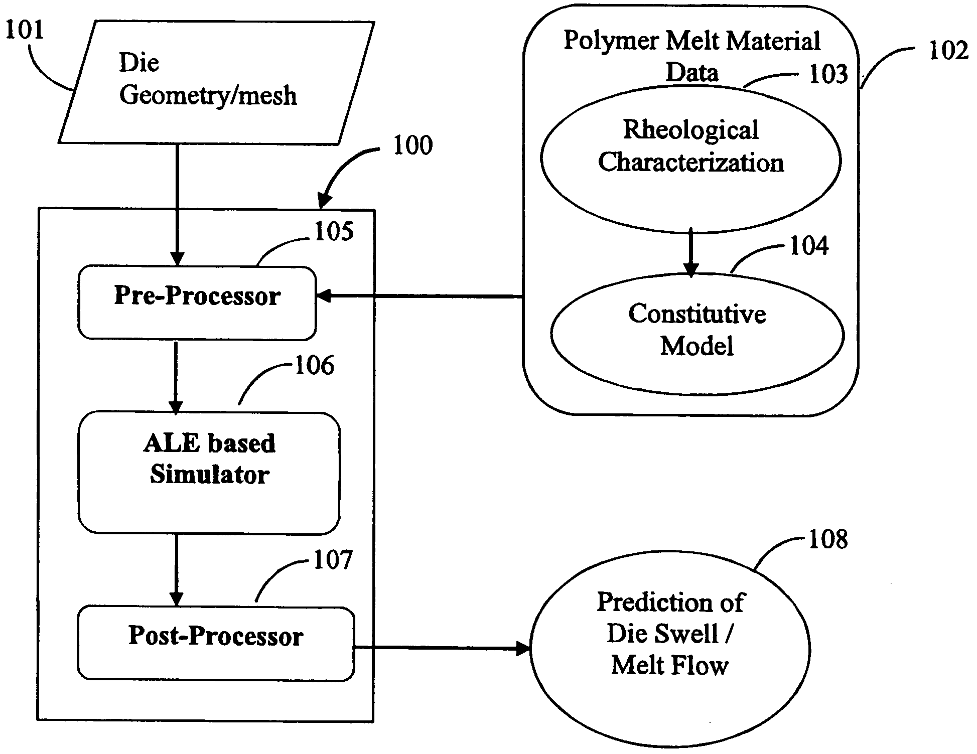
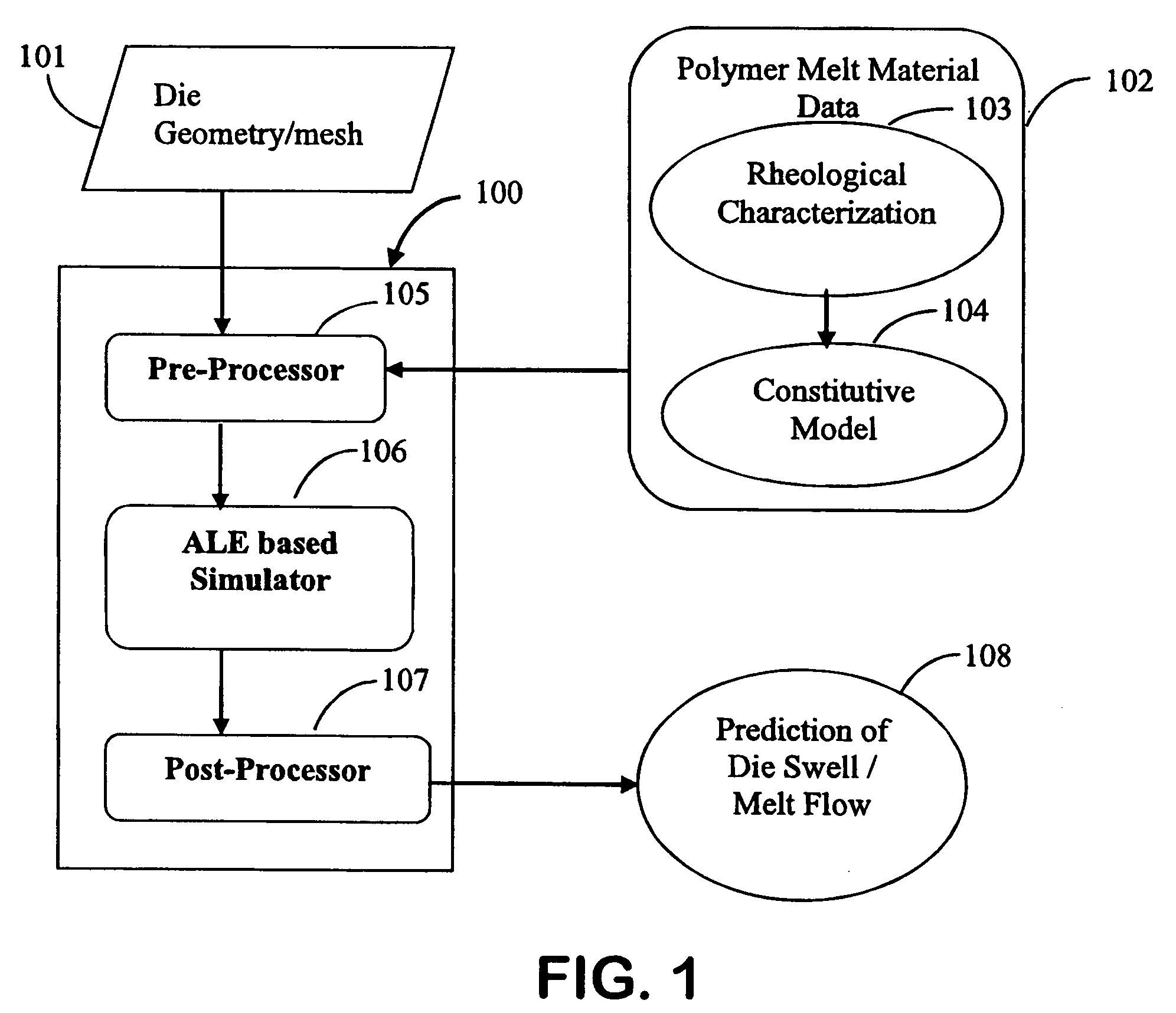
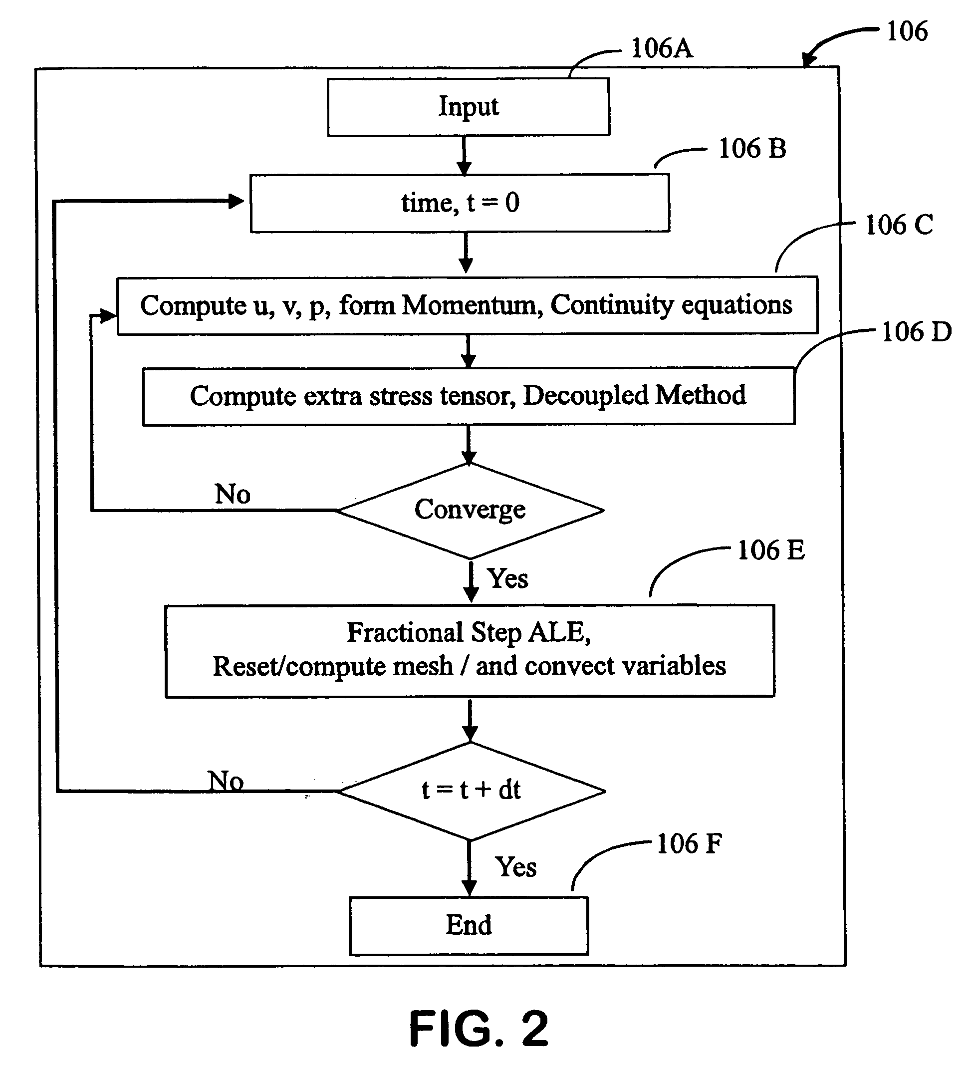
The present invention discloses a system for analyzing and simulating the die swell and the flow profile in polymer melt extrusion through a die, said system typically comprising a mesh generator adapted to generate a computational mesh; a pre-processor adapted to obtain die parameters, boundary conditions, polymer melt parameters including rheological characterization and constitutive equations and to generate an input file; a simulator adapted to receive the input file from the pre-processor and process the input data to simulate die swell; a mesh corrector means adapted to analyze the die swell obtained from said simulator and to correct the motion of the computational mesh and polymer melt to converge the die swell; a post-processor means adapted to visualize the die swell and flow profiles for the polymer melt; and a database means adapted to store the die swell corresponding to the die, mesh and polymer melt parameters.

Description

FIELD OF THE INVENTION[0001]This invention relates to the field of polymer melt extrusion.[0002]Particularly, this invention relates to an optimized process to correct the die swell and to design a die used for polymer melt extrusion.BACKGROUND OF THE INVENTION[0003]In this specification, the following terms have the following definitions as given alongside. These are additions to the usual definitions expressed in the art.[0004]Extrusion is a process used to create objects of a fixed cross-sectional profile in which a material is pushed or drawn through a die of a desired cross-section.[0005]Die is a specialized tool used in the manufacturing industry to shape or cut polymeric materials, metallic materials and the like.[0006]Die swell is the phenomenon by which a polymer after exiting from a die partially recovers or ‘swells back’ towards the former shape and volume. Die swell occurs when a polymer melt gains uniform velocity across the section after exiting from the die.[0007]Die ...

Claims


Application Information

Patent Timeline
IPC IPC(8): G06F15/00B29C48/06B29C48/08B29C48/09
CPCB29C47/003B29C47/06B29C47/0854G06F2217/16B29C47/20G06F17/5018B29C47/14B29C48/12B29C48/18B29C48/251B29C48/305B29C48/32G06F2111/10G06F30/23B29C48/08B29C48/06B29C48/09
Inventor GANVIR, VIVEKBASAVARSU, GAUTHAM PURUSHOTTHAMASHISH, LELEROCHISH, THAOKAR
Owner TATA CONSULTANCY SERVICES LTD
Why Eureka
Eureka Blog
Learn More