Microgrooves as Wick Structures in Heat Pipes and Method for Fabricating the Same

a technology of microgrooves and heat pipes, which is applied in the field of microgrooves, can solve the problems of large groove size (about >0.35 mm wide), high manufacturing cost, and inability to meet the requirements of the customer, and achieve the effect of increasing capillary for

Inactive Publication Date: 2009-08-27
ZHENG WEN CHUN
View PDF12 Cites 11 Cited by
  • Summary
  • Abstract
  • Description
  • Claims
  • Application Information

AI Technical Summary

Benefits of technology

[0016]In accordance with the invention, one embodiment of a method for fabricating microgrooves on a metal plate or strip includes two sequential steps in a single pass. A first blade with first multi-plowshares is used in the first step to turn up material on the plate or strip to form large grooves, and then a second blade with second multi-plowshares is used in the second step to rebury the large size grooves with the material turned up in the first step to form microgrooves. The microgrooves can have various shapes and are used as wicks in heat pipes. The microgrooves are formed from the relative movement between the blades and the plate or strip into which the plowshares enter. As the microgrooves can be fabricated with very small dimensions, which are controlled by the amount of the reburied material, the heat pipes can perform at large working angles due to increased capillary force.

Problems solved by technology

However, it is complex and expensive to manufacture this type of heat pipes, and the thermal resistance is higher than other type heat pipes because the sintered metal powders are porous.
Furthermore, they are also expensive and complicated to be manufactured.
However, they are only used at horizontal condition or small angles because the conventional grooves do not provide enough capillary force.
However, the size of the grooves are large (about >0.35 mm wide) relative to heat pipe dimensions due to the limitations on the tooling.
The resulting capillary force is not large enough to pump the working fluid back to the upper condenser at large working angles.

Method used


Image

  • Microgrooves as Wick Structures in Heat Pipes and Method for Fabricating the Same
  • Microgrooves as Wick Structures in Heat Pipes and Method for Fabricating the Same
  • Microgrooves as Wick Structures in Heat Pipes and Method for Fabricating the Same

Examples


Embodiment Construction

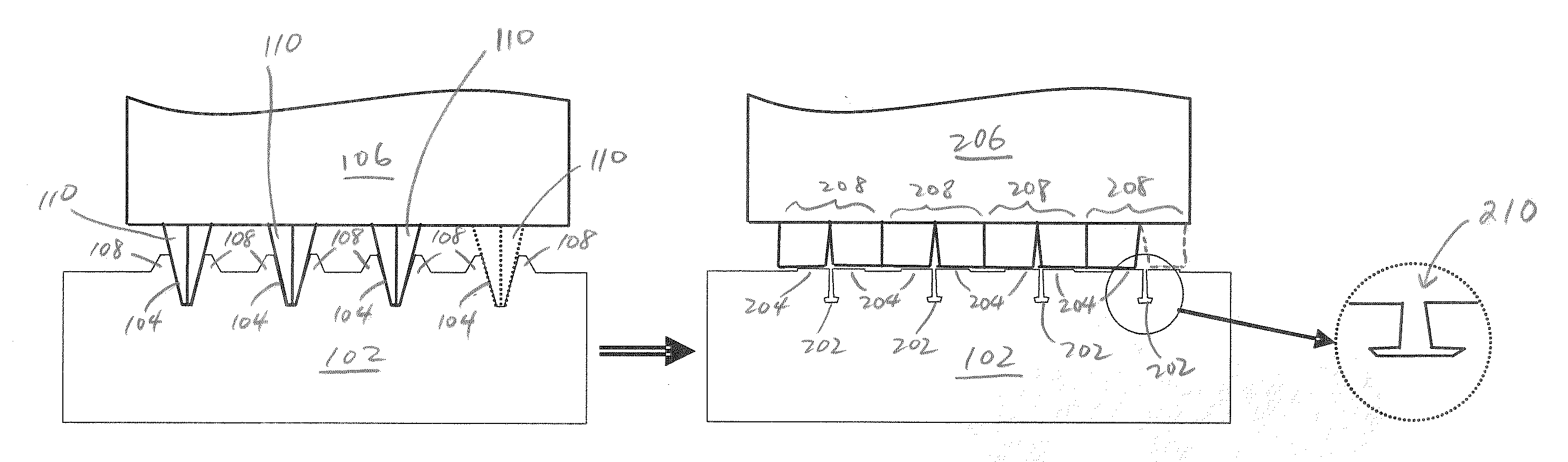
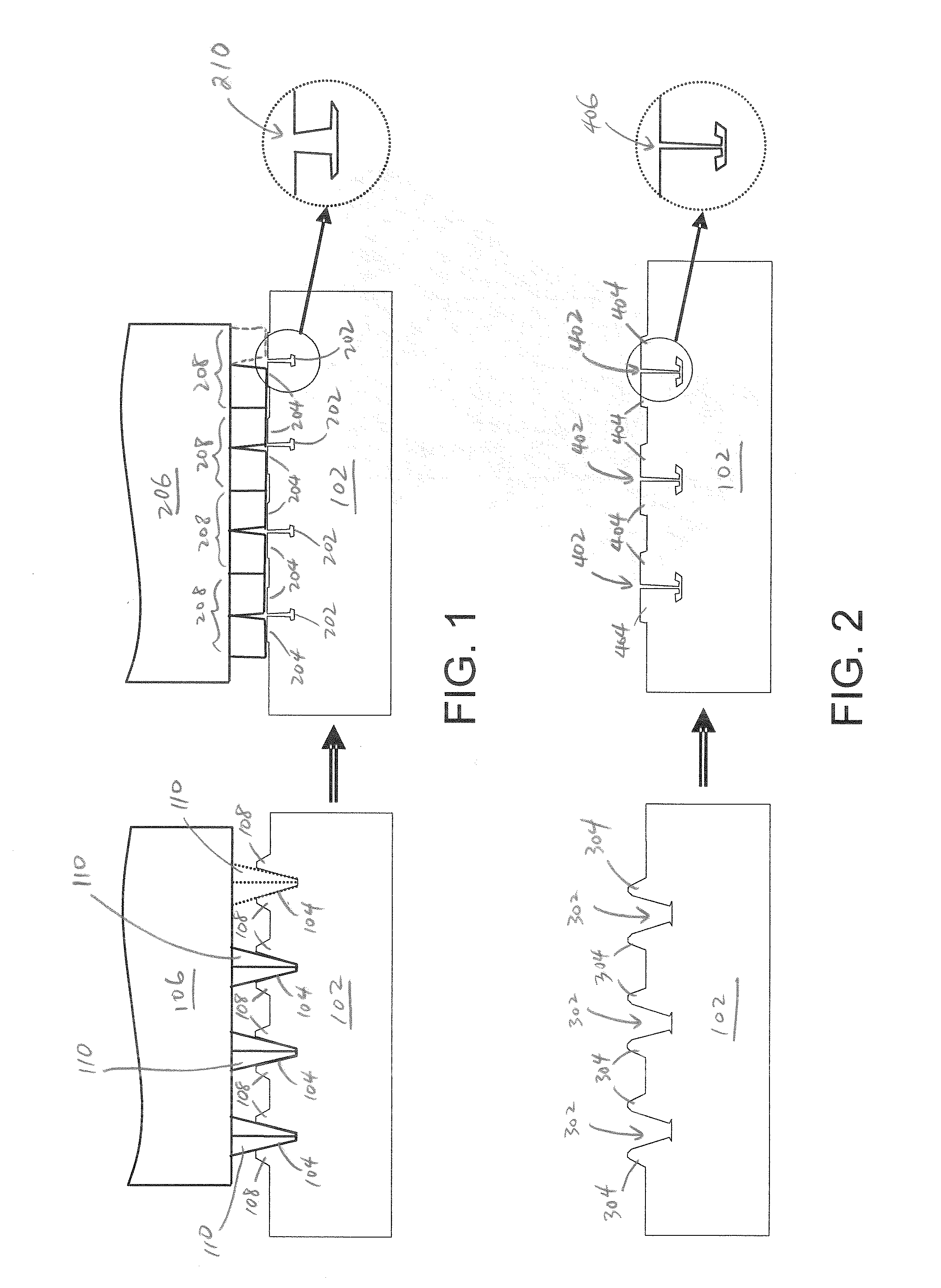
[0019]It is well known that narrow grooves provide large capillary force and therefore large working angle for heat pipes. Grooves of various shapes in current heat pipes are typically formed by extrusion and are generally greater than 0.3 mm wide. The microgrooves in accordance with the invention are mini / micro-scaled grooves that are less than 0.2 mm wide. The two sequential steps in accordance with the invention may be the only available approach for mass producing grooves of this scale at present time. The principle is as simple as a farmer plowing a trench in the soil and then reburying the trench after seeds are planted. To accomplish the process, two blades are used. A first blade of first multi-plowshares is used in the first step to turn up material on a metal plate or strip to form large grooves, and then a second blade with second multi-plowshares is used in the second step to rebury the large size grooves with the material turned up in the first step to form microgrooves...


PUM

PropertyMeasurementUnit
widthaaaaaaaaaa
sizeaaaaaaaaaa
widthaaaaaaaaaa

Abstract

Microgrooves (<0.2 mm wide) of various shapes used as wick structures in heat pipes can increase the capillary force to overcome the gravitational force on the working fluid so as to enable large working angles for the heat pipes. The microgrooves can be fabricated by two sequential steps use a first plowshare-like blade to turn up the material for large size grooves and then immediately use a second plowshare-like blade to rebury by the previously turned up material. The microgrooves and the fabrication method can be used to manufacture flat heat pipes (vapor chambers) as well as tubular heat pipes.

Description

FIELD OF INVENTION[0001]This invention is related to the wick structures, and more specifically to microgrooves (<0.2 mm wide) used as wick structures in heat pipes and method for manufacturing the same.DESCRIPTION OF RELATED ART[0002]A heat pipe is a highly efficient heat transfer device that typically includes a vacuum vessel. The vacuum vessel has a wick structure on its inner wall and contains a small quantity of working fluid. When a heat source is applied to an evaporator portion, the working fluid evaporates into vapor that spreads quickly in the vessel. The vapor carries latent heat to a condenser portion and condenses to liquid as the latent heat dissipates to outside of the heat pipe by conduction or convection. The working fluid is transported by the capillary force back to the evaporator portion, thereby completing a two phase heat transfer cycle without consuming any power.[0003]Generally, heat pipes are made from highly thermally conductive metals such as stainless ...

Claims


Application Information

Patent Timeline
Patent Type & Authority Applications(United States)
IPC IPC(8): B23P6/00
CPCB21C37/151B21C37/20B21C37/202B21J5/12Y10T29/49353B23P15/26B23P2700/09F28D15/0233F28D15/046B21K23/00
Inventor ZHENG, WEN-CHUN
Owner ZHENG WEN CHUN
Why Eureka
Try Eureka