Pressure sensor

a technology of pressure sensor and pressure sensor, which is applied in the direction of fluid pressure measurement by electric/magnetic elements, measurement devices, instruments, etc., can solve problems such as adulteration of measurement, and achieve the effect of different deformation behaviour

Inactive Publication Date: 2009-08-27
GRUNDFOS
View PDF15 Cites 9 Cited by
  • Summary
  • Abstract
  • Description
  • Claims
  • Application Information

AI Technical Summary

Benefits of technology

[0010]According to the invention, thus one may do away with compensation resistances arranged on the substrate. This, on the one hand permits the pressure sensor to be designed smaller, since the substrate, or the carrier does not have to be designed so large, that the compensation resistances may be arranged adequately far from the membrane. Furthermore, the arrangement according to the invention has the advantage that the first as well as the second measurement element react to deflections of the membrane on account of changes of the differential pressure. This means that both measurement elements actively take part in the measurement of the differential pressure. There are no longer any compensation resistances which are merely provided for compensating the system pressure, but do not react to the differential pressure. In this manner, the passive resistance in the circuit is reduced on differential pressure measurement, so that higher measurement accuracy is achieved.
[0011]Advantageously, the at least one first measurement element is arranged in an edge region of the membrane, and the at least one second measurement element is arranged in a central region or in a neutral region of the membrane which is situated between the edge- and central region. Alternatively, in a further preferred arrangement, the at least one second measurement element is arranged in a central region of the membrane, and the at least one first measurement element is arranged in an edge region or in a neutral region of the membrane which is situated between the edge region and the central region. This arrangement ensures that the first and the second measurement elements are distributed on the membrane, such that the influence of the system pressure on the output signals of the two measurement elements is different. In the case that the first measurement element or the first measurement elements are arranged in the edge region of the membrane, and the second measurement element or the second measurement elements are arranged in the central region of the membrane, the stresses or stress changes occurring on account of the system pressure and are detected by the first and the second measurement elements, have the same polarity, whilst the stress changes have different polarities on account of the differential pressure at both measurement elements or both groups of measurement elements. If one of the measurement elements is arranged in the neutral region, the differential pressure has no influence on this measurement element whatsoever, whilst it has an influence on the other measurement element or the other groups of measurement elements which are arranged outside the neutral region. However, the system pressure which acts on the membrane also has an influence on the measurement element in the neutral region of the membrane. It is thus possible with a suitable circuiting of the output signals of the first and second measurement elements or by way of the suitable evaluation of the exit signals, to detect the differential pressure and the system pressure or to compensate the influence of the system pressure on the detected differential pressure between both sides of the membrane.
[0013]The four first and the four second measurement elements thereby are preferably in each case designed or arranged, such that two of them have an output signal with a positive polarity and two of them have an output signal with a negative polarity. This means two first measurement elements have an exit signal with a positive polarity, and two second measurement elements have an output signal with a negative polarity. Accordingly, two second measurement elements could have an output signal with a positive polarity, and the two other second measurement elements an output signal with a negative polarity. This arrangement permits a simple common evaluation of the output signals of the first and second measurement elements. Thus in a bridge circuit, in which the first and second measurement elements are circuited to one another, for example in a Wheatstone bridge circuit, the output signals with a negative polarity may be very easily subtracted from the output signals with a positive polarity. One does away with complicated evaluation electronics which carry out these computation operations, and rather, the necessary additions and subtractions may be realised in a very simple manner in a simple bridge circuit, in which for example accordingly the resistance changes of the measurement elements may be subtracted from one another on account of their different polarities.
[0015]The membrane is furthermore preferably designed such that along a first axis, it has different deformation behaviour with a pressure impingement than along a second axis extending normally to the first axis. This arrangement is advantageous with the use of bi-directional measurement elements, i.e. of measurement elements which detect a total stress condition in both axis directions of the membrane plane. By way of a design in a manner such that the membrane has different deformation behaviour along its two axes normal to one another, in particular one succeeds in the influence of the system pressure on the deformation or stresses of the membrane being different along the two axes. The system pressure which acts on both membrane surfaces normal to the membrane surface, has no direct influence on the reading of the differential pressure, since this pressure acts in the same manner on both surfaces of the membrane. The system pressure has essentially an influence on the measurement result, only to the extent that it acts on the end-faces of the carrier or substrate at the edge of the membrane in a direction parallel to the membrane surface. If then, the membrane is designed such that it has a different deformation behaviour along the two axes, the forces which act on the edges of the substrate and which act on the membrane in a direction parallel to its surface, lead to different stresses along the two axes of the membrane surface normal to one another, on account of the differently long edges. Advantageously, the stresses or forces in the one direction are significantly larger than in the other direction, so that the low forces may be neglected. This permits stress changes to be able to be detected on account of the system pressure also with bi-directional measurement elements in the middle or in the central region of the membrane. Even if the previously described design of the membrane is particularly advantageous with the use of bi-directional measurement elements, it may also be applied to unidirectional measurement elements.
[0016]The first and second measurement elements are advantageously connected to one another into a common bridge circuit, for example a Wheatstone bridge circuit. This has the advantage that the sensor only emits an output signal which is proportional to the differential pressure to be detected. This output signal is already corrected from the influence of the system pressure acting on both sides of the membrane. It is therefore not necessary to determine the differential pressure and system pressure independently of one another, and to subsequently process the two respective signals such that the influence of the system pressure on the detected differential pressure value is compensated. However, it is also possible with the design according to the invention, to provide connection points in a common circuiting of the first and second measurement elements, at which a signal which is proportional to the system pressure may be tapped, in order to be able to also determine the system pressure with regard to numbers.
[0019]Preferably, the measurement elements are arranged in a region or regions of the membrane, in which the largest deformation occurs when impinged by pressure. As mentioned above, the membrane may be designed such that it has a different strain- or deformation behaviour along two axes normal to one another. In this case, the measurement elements are arranged for example along a zone, in which the greatest deformation behaviour of the membrane occurs with a pressure impingement. In this manner, the sensitivity and measurement accuracy of the pressure sensor is increased. Furthermore, the measurement elements are also arranged in the edge region of the membrane, where the largest deformations or stresses occur given a pressure impingement of the membrane.

Problems solved by technology

If such a pressure sensor is arranged in a system, for example a hydraulic system, a system pressure further acts on both sides of the membrane and the surrounding carrier, which may adulterate the measurement result.

Method used


Image

  • Pressure sensor
  • Pressure sensor
  • Pressure sensor

Examples


Embodiment Construction

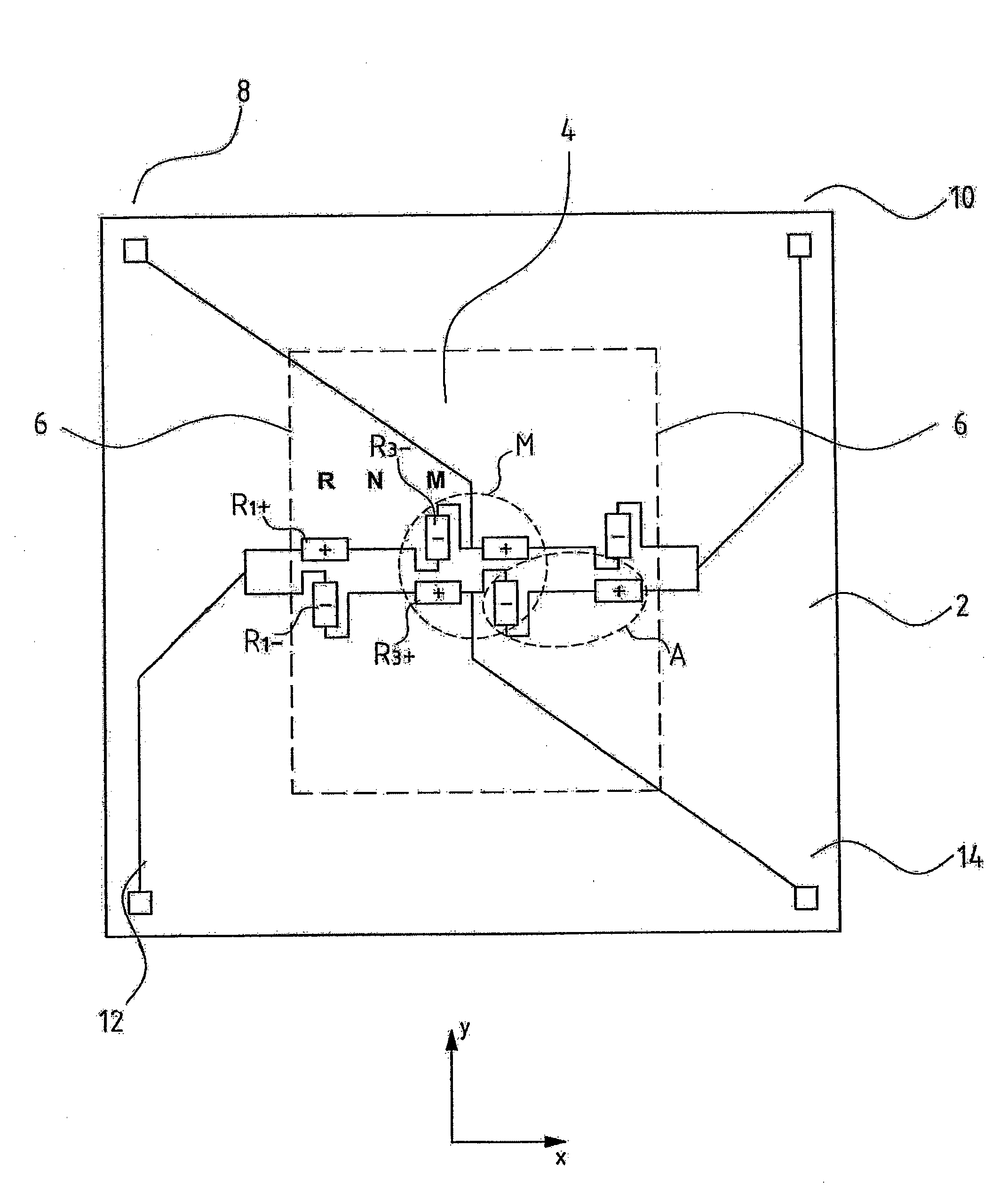
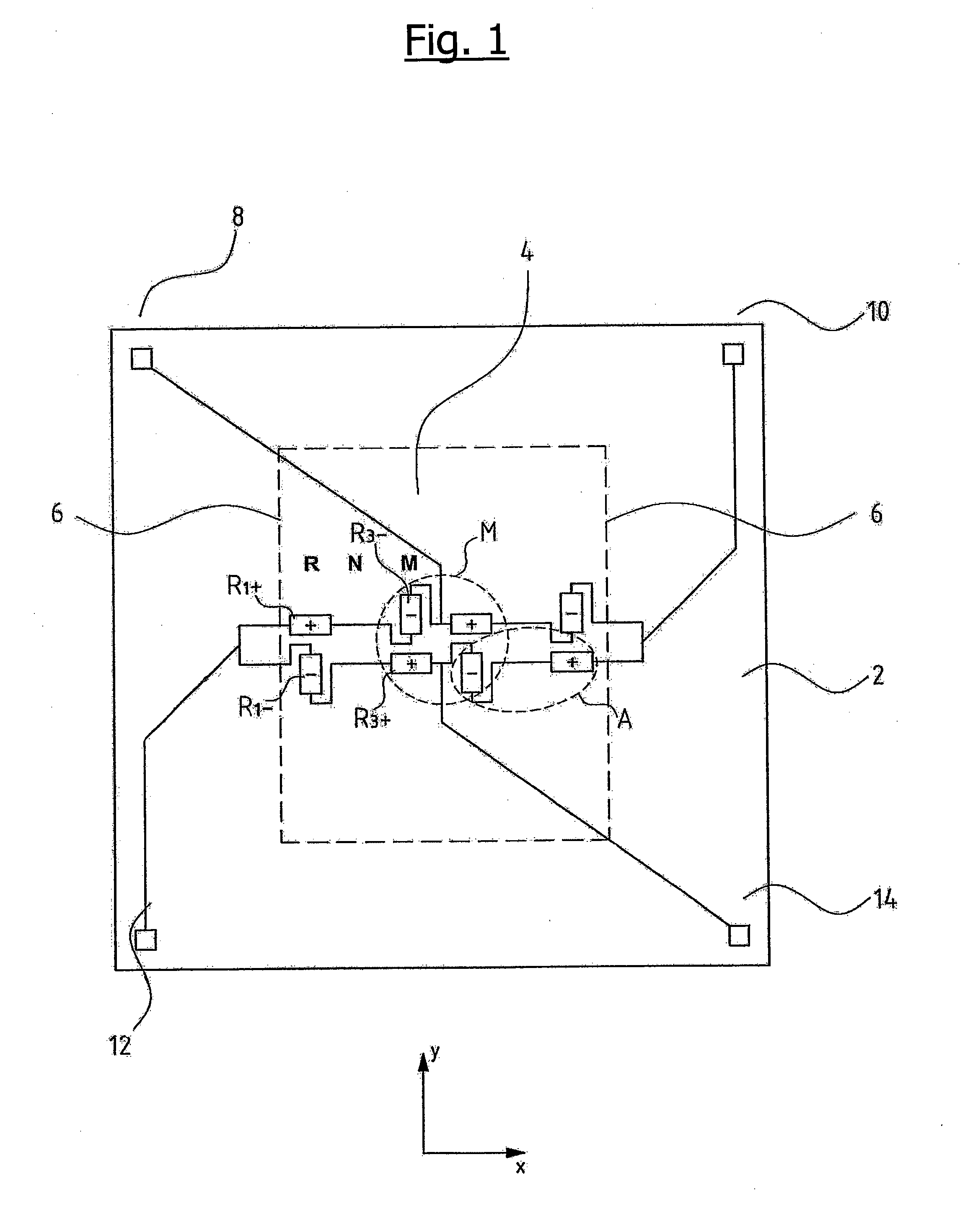
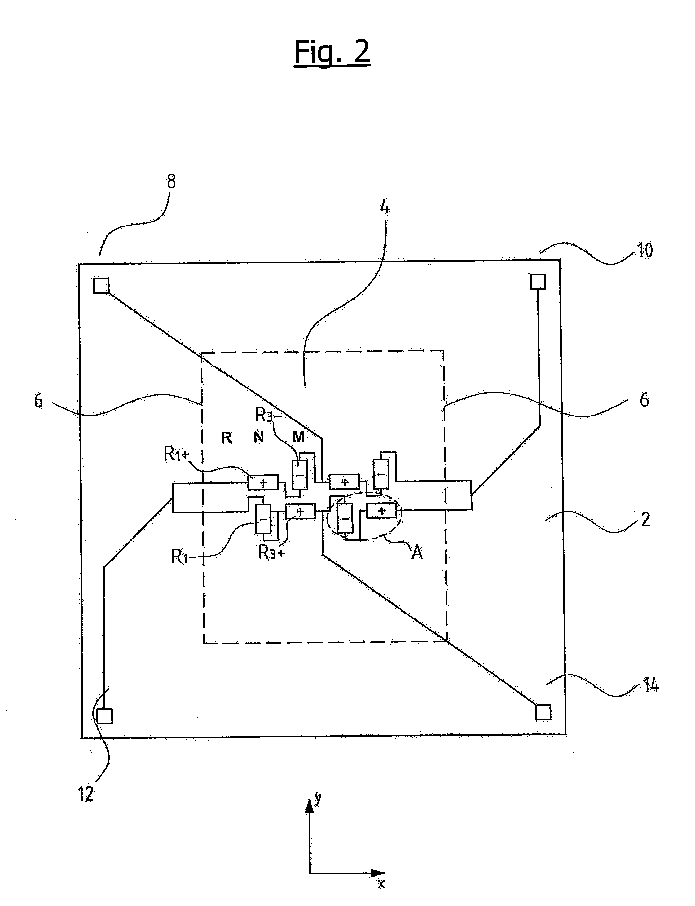
[0042]The pressure sensor according to the invention explained by way of the figures comprises a carrier or a substrate 2 of a semiconductor material, in whose middle region a rectangular membrane 4 is formed as one piece with the carrier 2 by way of thinning. The membrane is designed such that in the direction of the axis y, it has a greater edge length than in the direction of the axis x. The membrane in a known manner may be impinged from both surfaces with a pressure, in order to be able to determine the differential pressure between the two pressures prevailing at the opposite surfaces of the membrane, on account of the deflection of the membrane. For this, eight measurement elements in the form of measurement resistances are arranged on the membrane. With regard to the embodiment examples according to FIG. 1 to 3, the measurement resistances are formed by way of doping the semiconductor material as piezoresistive elements directly in the membrane surface. Four measurement resi...


PUM

PropertyMeasurementUnit
pressureaaaaaaaaaa
resistancesaaaaaaaaaa
compensation resistancesaaaaaaaaaa

Abstract

A pressure sensor is provided with a carrier (2), which in an inner region includes a membrane (4) on which at least one first measurement element (R1−) for detecting a pressure impingement of the membrane (4) is arranged. Additionally, at least one second measurement element (R3−) for detecting a pressure impingement of the membrane (4) is arranged on the membrane. The first measurement element (R1−) and the second measurement element (R3−) are arranged distanced differently far from the edge of the membrane. The output signals of the first and the second measurement element (R1−, R3−) are evaluated together in a manner such that the two measurement elements (R1−, R3−) detect a differential pressure acting on the membrane (4), and thereby compensate the influence of the system pressure acting on both sides of the membrane (4).

Description

CROSS-REFERENCE TO RELATED APPLICATIONS[0001]This application is a continuation application of U.S. patent application Ser. No. 11 / 575,829, filed on Aug. 2, 2007, currently pending, entitled “Pressure Sensor,” which is a Section 371 of International Application No. PCT / EP2005 / 008550, filed Aug. 6, 2005, which was published in the German language on Apr. 6, 2006, under International Publication No. WO 2006 / 034751 A1, the entire contents of all of which are incorporated herein by reference.BACKGROUND OF THE INVENTION[0002]The invention relates to a pressure sensor, in particular to a differential pressure sensor.[0003]Such a pressure sensor is for example known from EP 0 083 496 B 1 or from the European Patent application 03 015 055. These differential pressure sensors are formed from a semiconductor substrate, which is thinned in an inner region into a membrane. Four measurement resistances are arranged in this inner region, which are connected into a measurement bridge, so that one ...

Claims


Application Information

Patent Timeline
Patent Type & Authority Applications(United States)
IPC IPC(8): G01L13/02
CPCG01L9/0054
Inventor KROG, JENS PETERPEDERSEN, CASPERCHRISTENSEN, CARSTEN
Owner GRUNDFOS
Why Eureka
Try Eureka