Method for printing on spherical object and pad to be used therefor

a printing method and a technology for spherical objects, applied in the field of printing methods on spherical objects and the use of pads therefor, can solve the problems of troublesome photoengraving work, low productivity, and increase in printed faces, and achieve the effect of reducing the burden on photoengraving work and reducing the cost of production

Active Publication Date: 2009-08-27
BRIDGESTONE SPORTS
View PDF5 Cites 19 Cited by
  • Summary
  • Abstract
  • Description
  • Claims
  • Application Information

AI Technical Summary

Benefits of technology

[0006]The present invention has been made to solve the above problems, and accordingly an object of the present invention is provide a printing method in which at least approximately hemispherical portion of a spherical object to be printed can be printed by pressing a pad against the portion one time, and which can prevent an image printed on the spherical object to be printed from being elongated or distorted, and a printing pad used for this printing method.
[0009]The printing pad may have a columnar side surface adjacent to the transfer surface having a substantially hemispherical shape. The thickness of pad between the side surface and the inner surface may be larger than the thickness of pad between the transfer surface and the inner surface. The hardness of pad on the side surface may be higher than the hardness of pad on the transfer surface. A structure for enhancing the bending stiffness of pad may be arranged between the side surface and the inner surface. A cylindrical structure may be arranged so as to surround the outer periphery of the side surface. At least three notches may be located on the side surface.

Problems solved by technology

For the conventional pad printing system, there arises a problem as described below when an attempt is made to print the whole surface of a spherical object to be printed.
Therefore, in order to print the whole surface of a sphere, the pad must be pressed against the sphere many times at least four times, so that the productivity is low.
Also, in the case where a spherical surface is pad-printed, the photoengraving work is troublesome.
Therefore, the increase in printed face further imposes a burden on the photoengraving work.
Therefore, the increase in printed face also imposes a burden on the transferring work involving positioning work.

Method used


Image

  • Method for printing on spherical object and pad to be used therefor
  • Method for printing on spherical object and pad to be used therefor
  • Method for printing on spherical object and pad to be used therefor

Examples


Embodiment Construction

[0022]Embodiments of the present invention will now be described with reference to the accompanying drawings. The embodiments described below are examples for specifically explaining the present invention, and impose no restriction on the present invention.

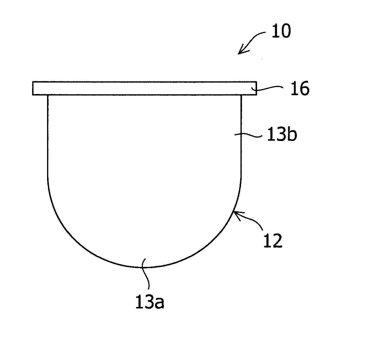
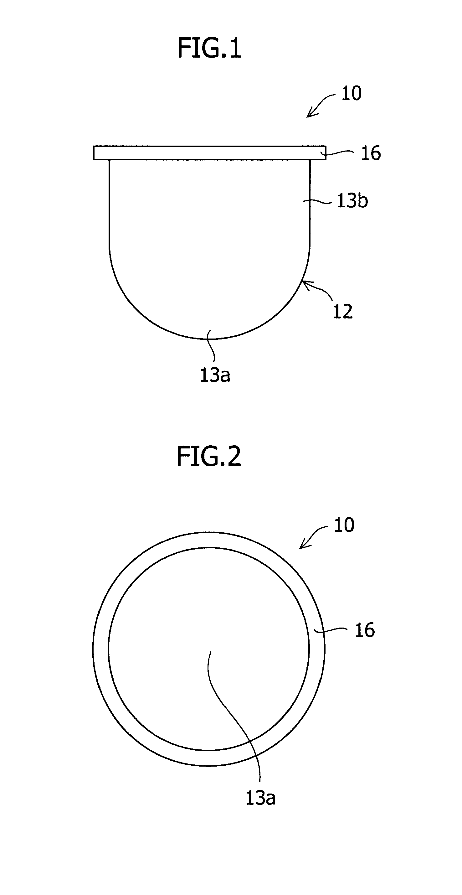
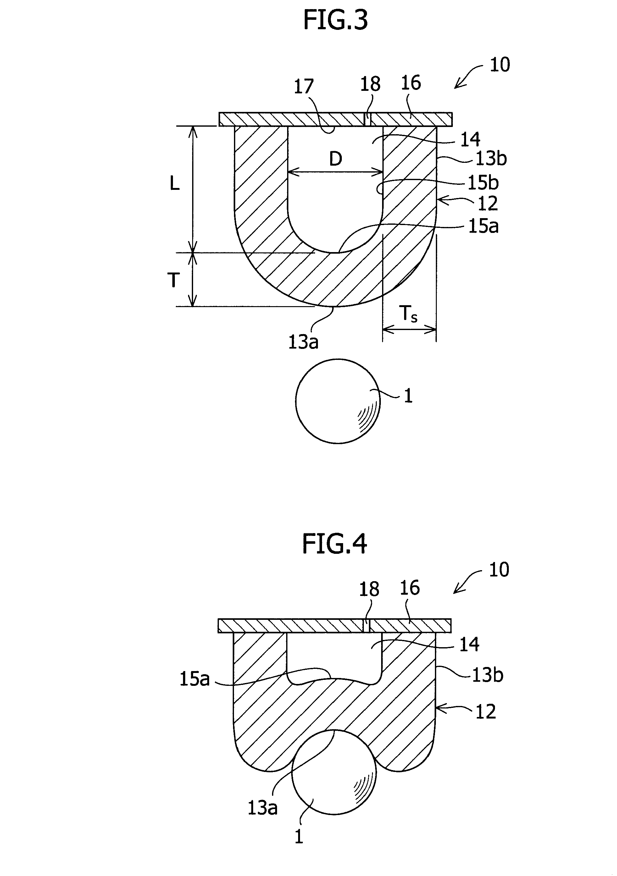
[0023]FIGS. 1 to 3 show a first embodiment of the present invention. As shown in FIGS. 1 and 2, a printing pad 10 of this embodiment includes a pad body 12 and a pad support part 16 for supporting the pad body 12. The pad body 12 has a transfer surface 13a at the tip end thereof on the side opposite to the end that joins to the pad support part 16. The transfer surface 13a is a part that comes into contact with a spherical object to be printed. In FIGS. 1 and 2, the transfer surface 13a having a substantially hemispherical shape is shown, but the transfer surface of the present invention is not limited to this shape. The pad body 12 has a columnar side surface 13b adjacent to the transfer surface 13a. The side surface 13b joins to...


PUM


Abstract

There are provided a printing method in which at least approximately hemispherical portion of a spherical object to be printed can be printed by pressing a pad against the portion one time, and which can prevent an image printed on the spherical object to be printed from being elongated or distorted, and a printing pad used for this printing method. The method for printing on the spherical object to be printed comprises the steps of preparing a hollow printing pad having a transfer surface, the printing pad being configured so that when the transfer surface is pushed, the gas in the hollow part is released to the outside of the printing pad; transferring ink or paint in recesses formed on the surface of a printing plate to the transfer surface of the printing pad by applying the ink or paint onto the surface of the printing plate and by pressing the transfer surface of the printing pad against the surface of the printing plate; and transferring the ink or paint, which has been transferred to the transfer surface of the printing pad, to the object to be printed by pressing the transfer surface of the printing pad, to which the ink or paint has been transferred, against the object to be printed until at least the hemispherical portion of the object to be printed is wrapped by the transfer surface of the printing pad.

Description

BACKGROUND OF THE INVENTION[0001]The present invention relates to a method for printing on a spherical object to be printed such as a golf ball. Also, the present invention relates to a pad used for such a printing method, and a golf ball on which printing is performed by such a printing method.[0002]As a device for printing images such as letters and pictures, a pad printing system has been used. The pad printing system has an elastic pad and operates as described below. On the surface of a printing plate, recesses are formed according to an image to be printed. Ink is applied onto the surface of the printing plate and fills the recesses. A pad is pressed against the surface of the printing plate, thereby transferring the ink in the recesses to the pad. Further, the pad is pressed against an object to be printed, by which the image is printed on the object to be printed. Since the pad has elasticity, the pad printing system can print images on not only a flat surface but also a cur...

Claims


Application Information

Patent Timeline
Patent Type & Authority Applications(United States)
IPC IPC(8): B41F3/34
CPCA63B45/02A63B2243/0029A63B2243/0083B41M1/40B41F17/30Y10S101/40B41F17/001A63B2102/32A63B2102/02
Inventor INOUE, NOBUYAOHIRA, TAKASHI
Owner BRIDGESTONE SPORTS
Why Eureka
Try Eureka