Air-fired co2 capture ready circulating fluidized bed heat generation with a reactor subsystem

a technology of air-fired co2 and fluidized bed, which is applied in the direction of lighting and heating apparatus, emission prevention, combustion types, etc., can solve the problems of many quarters adding coal-fired heat-generating system capacity, power availability, and system site itself being insufficient, so as to achieve less expense and greater efficiency

Active Publication Date: 2009-08-27
GENERAL ELECTRIC TECH GMBH
View PDF3 Cites 24 Cited by
  • Summary
  • Abstract
  • Description
  • Claims
  • Application Information

AI Technical Summary

Benefits of technology

[0012]Accordingly, it is an objective of the present invention to provide a technique for capturing CO2 generated by fossil fuel fired steam or other heat generating system that can be implemented at less expense and / or greater efficiency than known techniques.

Problems solved by technology

However, while the disclosed technique can be used to significantly reduce CO2 emissions, there remains a reluctance in many quarters to add coal fired heat generating system capacity because of concerns regarding the future governmental regulation CO2 emissions and the costs of meeting these regulations.
Furthermore, particularly in retrofit situations, the system site itself may be insufficient to accommodate an architecture of the type described in the '567 patent.
Thus, while there is a recognized need for more heat generating system capacity to, for example, produce additional electrical power, and it is also recognized that CFB coal fired systems are an efficient means to generate such heat, the ongoing debate over global warming, and the increasing attention being given to CO2 emissions from the burning of fossil fuels such as coal, and most particularly the cost of capturing CO2 in terms of both capital expense and reduced energy production, have undoubtedly delayed some if not many installations, which could increase capacity and thereby increase the availability of power to the nation and the world.

Method used


Image

  • Air-fired co2 capture ready circulating fluidized bed heat generation with a reactor subsystem
  • Air-fired co2 capture ready circulating fluidized bed heat generation with a reactor subsystem

Examples


Embodiment Construction

)

Common System Components and Associated Operations

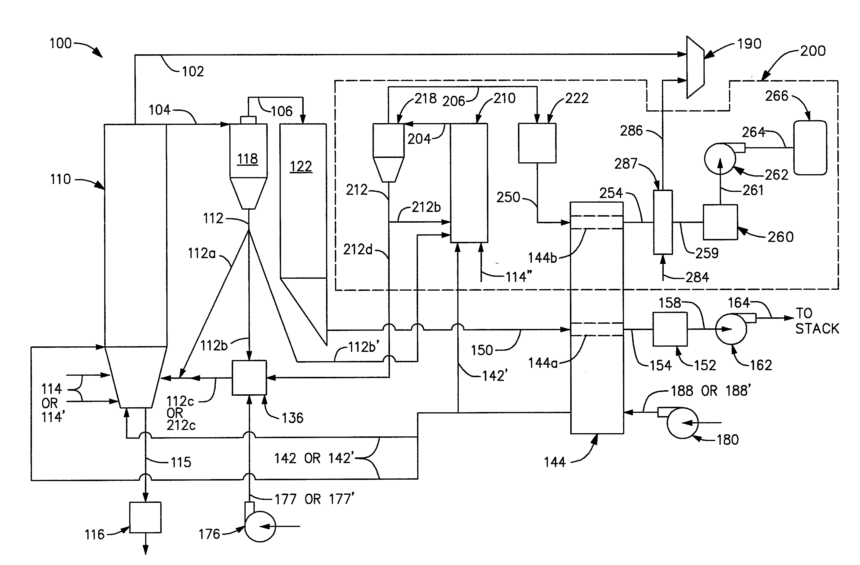
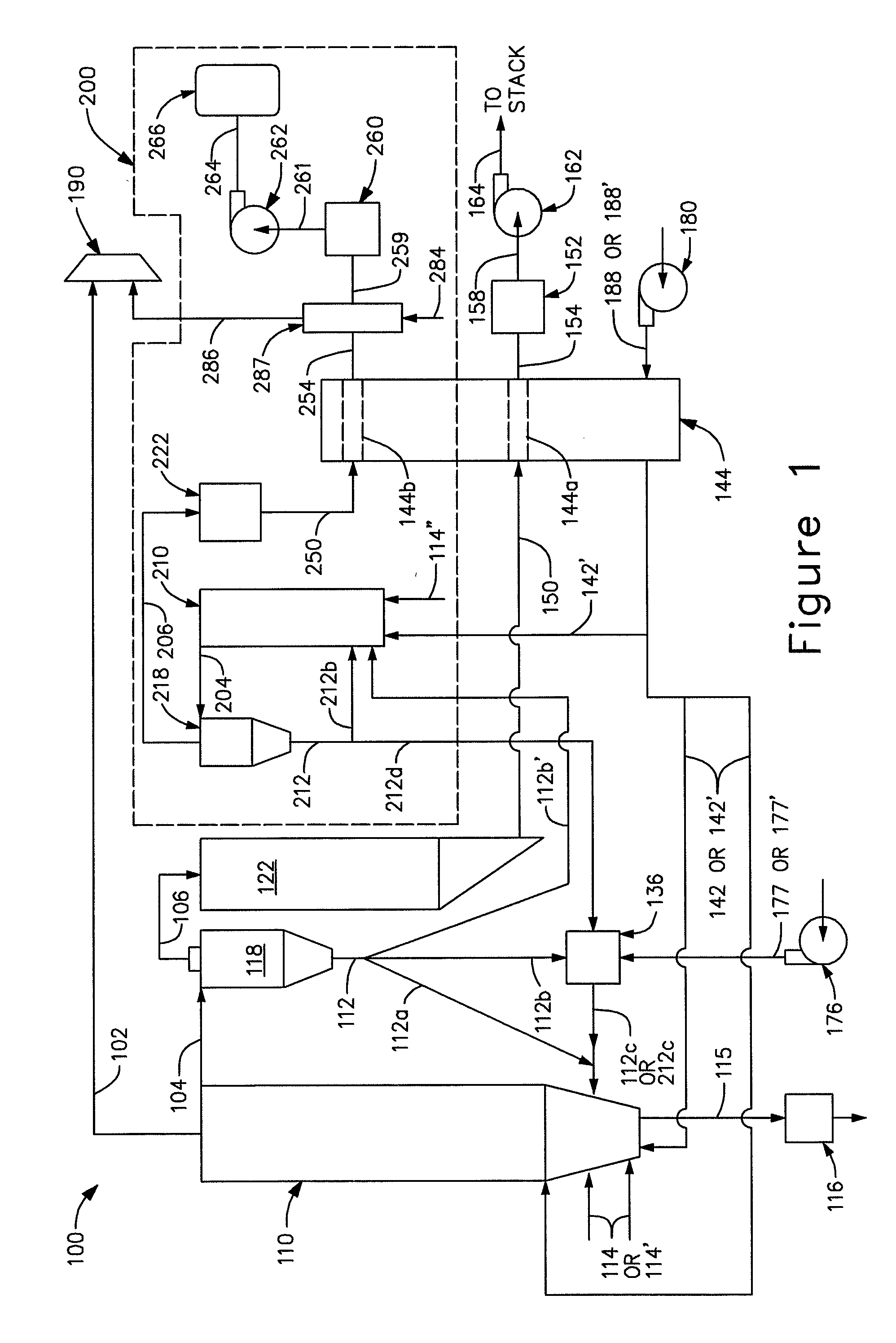
[0031]FIG. 1 depicts a schematic view of an exemplary air fired circulating fluidized bed (CFB) heat generating system 100, in accordance with the present invention. The CFB heat generating system 100, uses air to combust the fossil fuel.

[0032]In the particular exemplary implementation described below, the fossil fuel is pulverized coal. It should be understood that other types of fossil fuels could be utilized in lieu of pulverized coal, however preferably a fossil fuel with a high carbon content such as pulverized coal or petcoke, or a biomass is used. The working fluid is H2O, which may be in a liquid, gaseous or mixed liquid and gaseous state at different points in the process. However, here again it should be understood that other types of working fluids could be utilized in lieu of H2O. Furthermore, it will be understood that the working fluids which flow within various components could be of the same type or different types.

[...


PUM


Abstract

A combustor 110 combust a fluidized bed of fossil fuel 114, 114′ to heat a working fluid 102 and generate flue gas 104. An air preheater 144 has first and second gas passageways 144a, 144b for respectively directing the generated flue gas 150 and another gas 250 with captured CO2 generated by combustion outside of the combustor 110. When operated in a non-CO2 capture, the air preheater 144 receives the flue gas 150, but not the other gas 250, and the first gas passageway 144a directs the flue gas 150 so as to preheat the air 188. However, when operated in the CO2 capture mode, the air preheater 144 receives the flue gas 150 and the other gas 250, and the second gas passageway 144b also directs the other gas 250 so as to preheat the air 188′. In either mode, the preheated air 188, 188′ is applied by the combustor 110 to fluidize a bed of fossil fuel 114, 114′.

Description

RELATED APPLICATIONS[0001]The present invention claims benefit of co-pending U.S. Provisional Patent Application Ser. No. 61 / 031,764, entitled “AIR-FIRED CO2 CAPTURE READY CIRCULATING FLUIDIZED BED HEAT GENERATION”, and U.S. Provisional Patent Application Ser. No. 61 / 031,761, entitled “AIR-FIRED CO2 CAPTURE READY CIRCULATING FLUIDIZED BED HEAT GENERATION WITH A REACTOR SUBSYSTEM”, which are incorporated herein by reference in their entirety.FIELD OF THE INVENTION[0002]The present invention relates generally to heat generation. More particularly, the present invention relates to air-fired CO2 capture ready fluidized bed heat generation. The invention is particularly suitable for designing air fired circulating fluidized bed heat generating systems for subsequent CO2 capture.BACKGROUND OF THE INVENTION[0003]Heat generating systems with furnaces for combusting fossil fuels have long been employed to generate controlled heat, with the objective of doing useful work. The work might be in...

Claims


Application Information

Patent Timeline
Patent Type & Authority Applications(United States)
IPC IPC(8): F23J3/00
CPCF22B31/0007F23C9/00F23C10/10F23J15/006F23J15/06F23J2215/50Y02E20/348F23L15/04F23L2900/07001F23L2900/07003F23L2900/15042Y02E20/322Y02E20/344F23L7/007Y02E20/32Y02E20/34
Inventor ANDRUS, JR., HERBERT E.LILJEDAHL, GREGORY N.MARION, JOHN L.NSAKALA, NSAKALA YA
Owner GENERAL ELECTRIC TECH GMBH
Why Eureka
Try Eureka