Sputtering apparatus and method for controlling the same

a technology of sputtering apparatus and sputtering method, which is applied in the direction of instruments, vacuum evaporation coatings, coatings, etc., can solve the problems of limited number of targets that can be sputtered simultaneously, the composition of formed thin films often deviating from the composition of targets, and the combination of targets, so as to increase the number of targets to be sputtered simultaneously, the degree of freedom of combining targets, and the effect of reducing costs

Active Publication Date: 2009-08-27
CANON ANELVA CORP
View PDF4 Cites 41 Cited by
  • Summary
  • Abstract
  • Description
  • Claims
  • Application Information

AI Technical Summary

Benefits of technology

[0009]An object of the present invention is to provide a multi-target sputtering apparatus including an increased number of targets that can be sputtered simultaneously, and a method for controlling the sputtering apparatus.
[0012]In the present invention, since the first and second shutter plates are rotated independently of each other, the degree of freedom of combining targets is increased, and thus, it is possible to increase the number of targets to be sputtered simultaneously. Accordingly, by using a sputtering apparatus of the present invention, it is possible to carry out the composition adjustment of thin films and the development of novel thin-film materials at even lower costs and in an even shorter period of time in a process of manufacturing a semiconductor device or an electronic device.

Problems solved by technology

However, the composition of the formed thin film often deviates from the composition of the target or the deposition material in the PVD method.
Thus, the work has required extra development costs and a prolonged period of time.
In the method disclosed in Japanese Patent Application Laid-Open No. 2005-256112, however, the combination of targets, and the number of targets that can be sputtered simultaneously, have been limited since one shutter plate is fixed as a shutter for cathode selection and the other shutter plate is used for open / close operations.

Method used


Image

  • Sputtering apparatus and method for controlling the same
  • Sputtering apparatus and method for controlling the same
  • Sputtering apparatus and method for controlling the same

Examples


examples

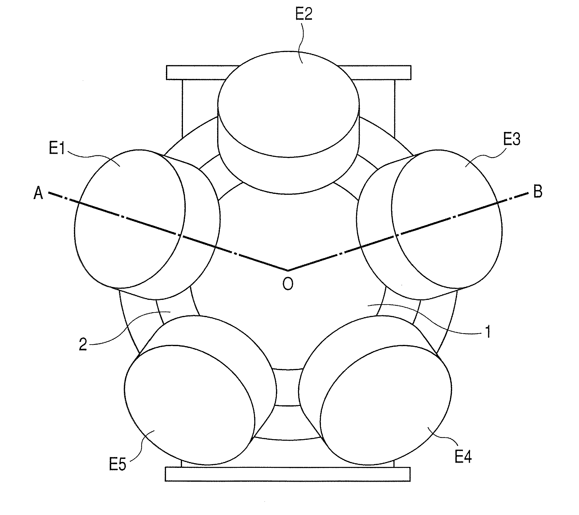
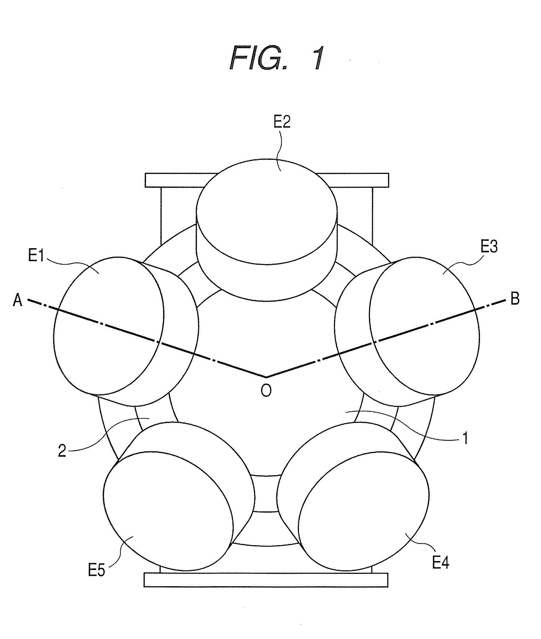
[0089]Using the sputtering apparatus shown in FIG. 1, three-target co-sputtering using magnetic targets 6 made respectively of Fe, Co and Ni plates was performed and various Fe—Co—Ni alloy thin films were fabricated.

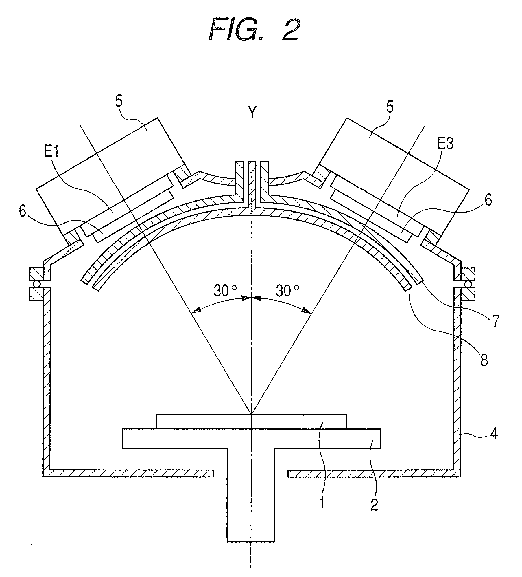
[0090]In the present example, an Si substrate 1, 300 mm in diameter, provided with a thermally-oxidized film was first placed on a substrate stage 2. Then, target electrodes E1 to E5 having a diameter of 180 mm were arranged and disk-shaped targets 6, 180 mm in diameter, were attached thereto. In the present example, the Fe, Co and Ni targets 6 were attached to target electrodes E1, E2 and E3, respectively.

[0091]First, a vacuum chamber 4 was roughly evacuated using a dry pump (unillustrated). Then, the dry pump was changed to a cryopump (unillustrated) to evacuate the vacuum chamber 4 up to an ultrahigh vacuum range of 7×10⁻⁷ Pa. After that, an Ar gas was introduced until a pressure of 0.03 Pa was reached, and first and second shutter plates 7 and 8 were arranged in a cl...


PUM

PropertyMeasurementUnit
tilt angleaaaaaaaaaa

Abstract

The present invention provides a multi-target sputtering apparatus including an increased number of targets which can be sputtered simultaneously, and a method for controlling the sputtering apparatus. In one embodiment of the present invention, first and second shutter plates are provided between a substrate and target electrodes and paths between intended targets and the substrate are shut off by the shutter plates to perform a pre-sputtering step. In addition, the first and second shutter plates are rotated as appropriate at the time of transition to a full-scale sputtering step, so as to overlap through-holes provided in the shutter plates, thereby opening up paths between the intended targets and the substrate. Then, a full-scale sputtering step is performed.

Description

CROSS-REFERENCES TO RELATED APPLICATIONS[0001]This application claims the benefit of priority from Japanese Patent Application No. 2008-039784 filed Feb. 21, 2008, the entire contents of which is incorporated herein by reference.BACKGROUND OF THE INVENTION[0002]1. Field of the Invention[0003]The present invention relates to a sputtering apparatus for forming thin films on a semiconductor substrate such as silicon, or on a substrate of metal, glass, ceramics, plastics or the like, in vacuum in a manufacturing process of a semiconductor device or an electronic device, and to a method for controlling the sputtering apparatus.[0004]2. Related Background Art[0005]In modern semiconductor devices and electronic devices, a complex alloy, compound or mixture has come into use for a material playing a central role along with the improvement of device performance. For a thin film composed of such a material, there has been conventionally used a target and a deposition material of a similar com...

Claims


Application Information

Patent Timeline
Patent Type & Authority Applications(United States)
IPC IPC(8): C23C14/38G06F17/00
CPCC23C14/165C23C14/352H01J37/3447H01J37/34C23C14/548H01L21/203
Inventor TSUNEKAWA, KOJI
Owner CANON ANELVA CORP
Why Eureka
Try Eureka