
Structural element

Active Publication Date: 2009-08-27
VOLVO LASTVAGNAR AB
View PDF2 Cites 0 Cited by
  • Summary
  • Abstract
  • Description
  • Claims
  • Application Information

AI Technical Summary

Benefits of technology

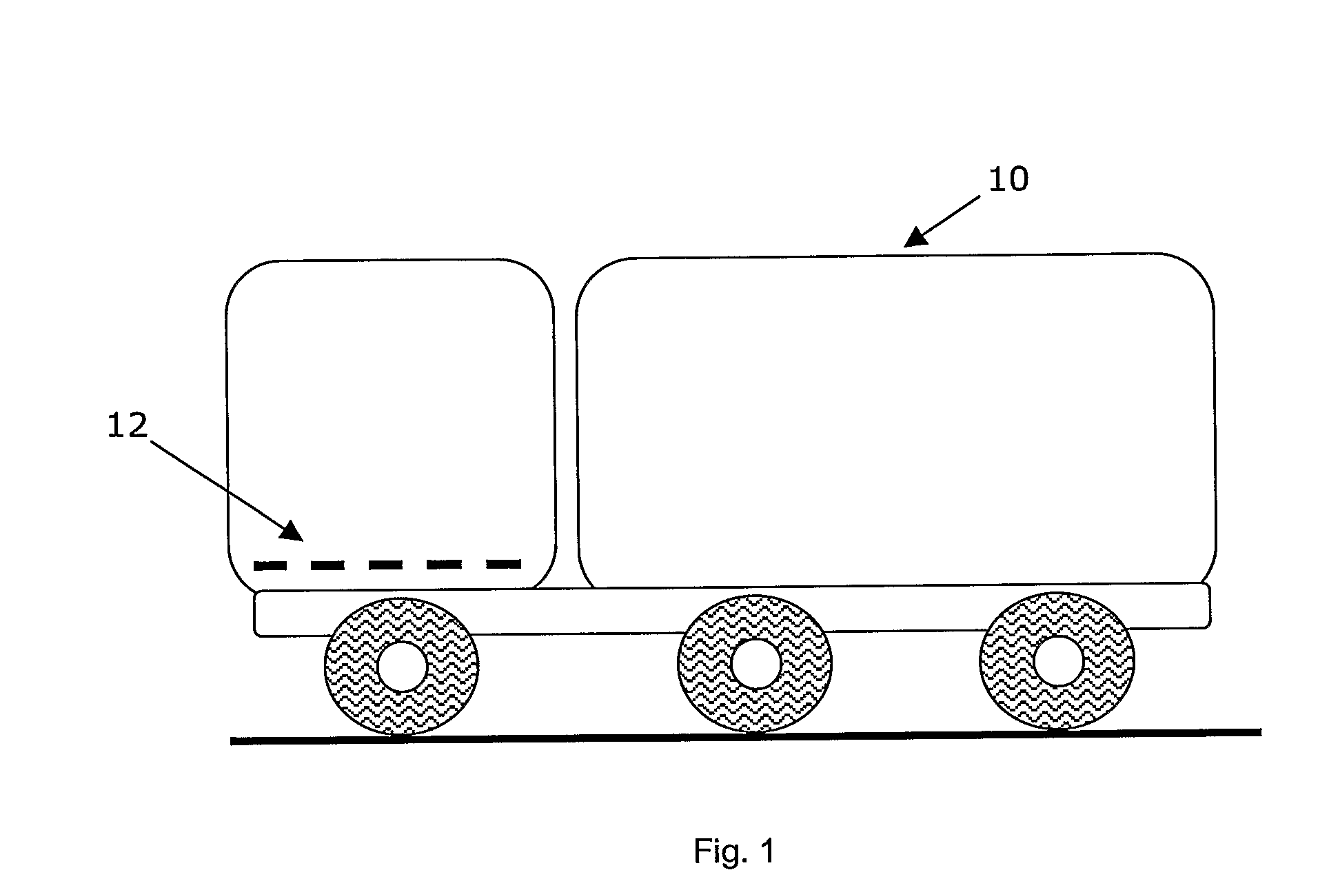
[0003]U.S. Pat. No. 6,793,276 discloses a vehicle floor that is partitioned into a plurality of substantially rectangular panels. These panels are arranged such that vibration of a 2×1 mode, in which two antinodes are generated in the length direction of the vehicle and one antinode is generated in the width direction of the vehicle, occurs in the floor panels when vibrations of a predetermined frequency, 240 to 260 Hz, are input to the floor panels from the outside of the vehicle. This means that two adjacent sections of each floor panel are made to vibrate with opposite phase but with the same amplitude so that the radiated sounds from each section cancel each other out and there is a considerable drop in the acoustic radiation efficiency and consequently road noise between 240 and 260 Hz can be reduced. Reinforcing members constituting the vehicle frame isolate each floor panel so that coupled vibration between said floor panels and other floor panels and surrounding structures is prevented and so that the intended 2×1 vibration mode can be excited in each floor panel.
[0005]It is desirable to provide a structural element, such as a panel or beam or a more complex structure, which will cause fewer vibration problems compared to known structural elements.
[0009]A significant performance improvement is achieved in comparison with conventional structural elements that utilize damping material, reinforcement ribs and beams or embossing patterns selected on other criteria by using the inventive structural element. The inventive embossed structural element will not only reduce noise radiated from it due to vibration but will also exhibit increased strength and rigidity due to its contoured or corrugated topography. Furthermore since no reinforcement structures or other material is added to the structural element it can be manufactured at reduced cost and weight compared to conventional structural elements. Further advantages are reduced annoyance, reduced human fatigue and drowsiness, improved safety and reliability.
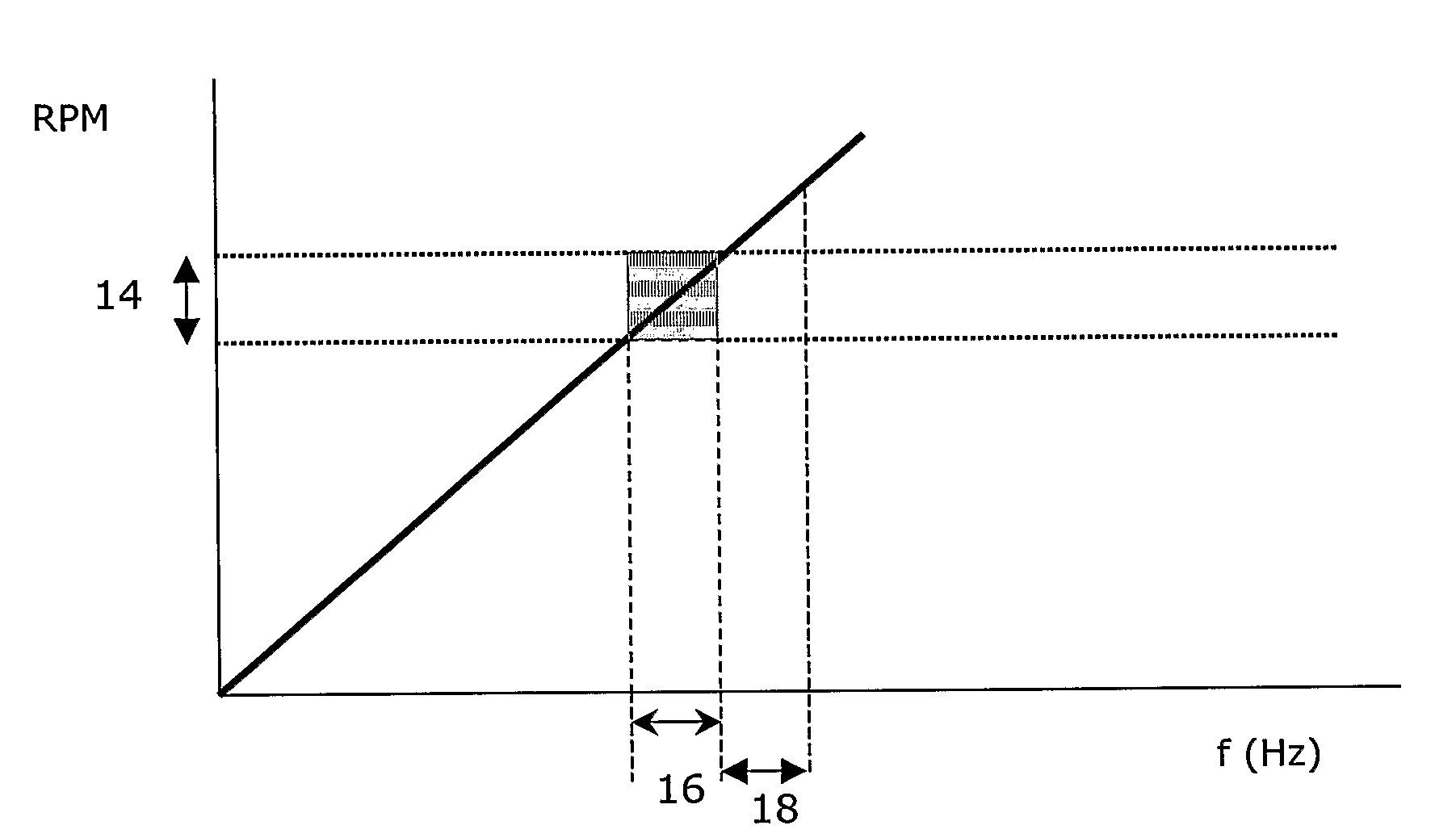
[0019]According to another embodiment of the invention the method comprises the step of selecting the mode shape that has at least one vibration mode within a desired frequency band, for example within a frequency band at which energy orders of an engine are expected to excite for only short time intervals. Alternatively or simultaneously a mode shape that has at least a local rigidity within a desired range of rigidity is selected i.e., depending on the application, part of the structural element or the entire structural element may be arranged to have a particular rigidity. The frequency of the first vibration mode of an embossed structural element is a good measure of the increase in rigidity of the embossed structural element as compared to a non-embossed structural element and is also an indicator of the reduction in vibration that can be expected.
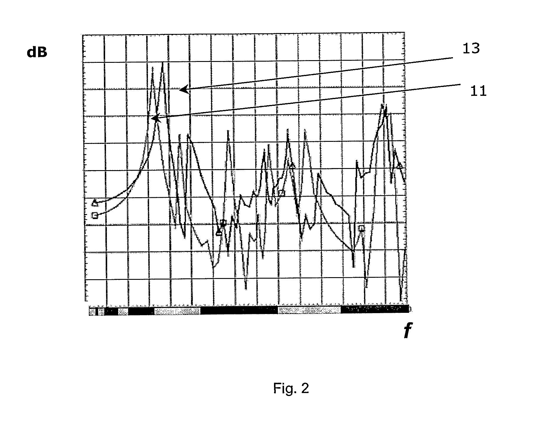
[0020]According to another embodiment of the invention the method comprises the step of determining the frequency at which there is a vibration related problem in the structural element and selecting a mode shape that reduces or eliminates the vibration problem at that frequency. According to a further embodiment of the method comprises the step of determining the frequency at which the most noise is radiated by the structural element and selecting a mode shape that reduces or eliminates noise transmission at that frequency. Noise transfer functions (NTFs) (i.e. Pa / N), acoustic transfer functions (Pa / m3 / s2) or uncoupled acoustic transfer vectors that relate the vibration of a structural element to sound pressure may for example be computed in a noise transmission analysis to identify the noisiest vibration modes of the structural element.

Problems solved by technology

Mechanical systems under cyclic loading, such as vehicles, fans or washing-machines, normally present structural vibrations.
These vibrations can cause noise and fatigue problems, they can annoy and disturb people in the vicinity of said systems and they can constitute a safety risk.
However, these solutions can not be always used because they can change the system design, weight or cost.
A disadvantage with such a system is that if vibration coupling is not suppressed the sound that is radiated from the floor panels becomes insufficiently cancelled.
Furthermore the vibration region of the floor panels must be substantially rectangular in order to generate vibrations in a 2×1 mode, which limits a vehicle manufacturer's design options.

Method used


Image

  • Structural element
  • Structural element
  • Structural element

Examples


example

[0043]Some calculations were made on a 1 m2 simply supported steel panel (1005×1005×0.8 mm) using FEM. The absolute values of the first 9 vibration modes of the steel panel were embossed onto nine panels of the same dimensions, i.e., a different mode was embossed on each panel, using three different amplification factors and the modes of each embossed steel panel were studied. The results showed that mode no. 4 provided the panel having the greatest rigidity. The embossed panel having a mode shape corresponding to mode 4 had a first mode at 121 , 159 and 194 Hz for maximum embossing depths of 30, 40 and 50 mm respectively. The first mode of the non-embossed, flat 1 m2 steel panel appeared at a frequency of 3.8 Hz. So using an amplification factor that resulted in a maximum embossing depth of 40 mm increased the frequency of the first mode by a factor of about 42 after the flat panel had been embossed.


PUM


Abstract

Structural element, such as a panel, which is embossed with a mode shape (φtotal), i.e. with any of the various stationary vibration modes (φn) of which the structural element is capable, or a combination thereof.

Description

BACKGROUND AND SUMMARY[0001]The present invention concerns a structural element, such as a panel, i.e. a piece of construction material made to form part of a surface whereby the width and height of the panel is large compared to its thickness. The structural element is intended for use in a vehicle, washing machine, fan or any other device that is subjected to transient and / or cyclic and / or random loading. The present invention also concerns a method for designing a structural element.[0002]Mechanical systems under cyclic loading, such as vehicles, fans or washing-machines, normally present structural vibrations. These vibrations can cause noise and fatigue problems, they can annoy and disturb people in the vicinity of said systems and they can constitute a safety risk. The vibration amplitudes can be partially reduced by using rigid or reinforced structures, by applying springs or other kinds of damping means or by using damping material to absorb the mechanical energy related to ...

Claims


Application Information

Patent Timeline
IPC IPC(8): B62D25/20B60R13/00G06F17/00B62D21/10B62D33/06G05D
CPCB60G2206/60B60G2206/722B62D33/06B62D21/10B62D25/20B60G2600/44
Inventor HEDLUND, ANDERSFREDO, CLAES
Owner VOLVO LASTVAGNAR AB
Learn More