Image mixing apparatus and pixel mixer

a mixing apparatus and mixer technology, applied in the field of image mixing apparatus and pixel mixer, can solve the problems of inability to freely determine display priority, inability to prepare mixed image data, and inability to mix image data items having different resolutions, etc., and achieve the effect of easy construction of an image mixing apparatus

Inactive Publication Date: 2009-08-27
SHINSEDAI KK
View PDF16 Cites 57 Cited by
  • Summary
  • Abstract
  • Description
  • Claims
  • Application Information

AI Technical Summary

Benefits of technology

[0032]By making use of the pixel mixer as described above, it is possible to easily construct an ima

Problems solved by technology

However, in accordance with such a prior art image processing system, it is impossible to mix image data items having different resolutions.
In addition to this, it is impossible to freely determine the display priority, which is depending upon the order of mixing the image

Method used


Image

  • Image mixing apparatus and pixel mixer
  • Image mixing apparatus and pixel mixer
  • Image mixing apparatus and pixel mixer

Examples


Embodiment Construction

[0054]In what follows, an embodiments of the present invention will be explained in conjunction with the accompanying drawings. Meanwhile, like references indicate the same or functionally similar elements throughout the respective drawings, and therefore redundant explanation is not repeated. Also, when it is necessary to specify a particular bit or bits of a signal in the description or the drawings, [a] or [a:b] is suffixed to the name of the signal. While [a] stands for the a-th bit of the signal, [a:b] stands for the a-th to b-th bits of the signal. In regard to the hexadecimal expression, “H” is suffixed to the number in order to distinguish it from the decimal expression. Also, while a prefixed “0b” is used to designate a binary number, a prefixed “0x” is used to designate a hexadecimal number.

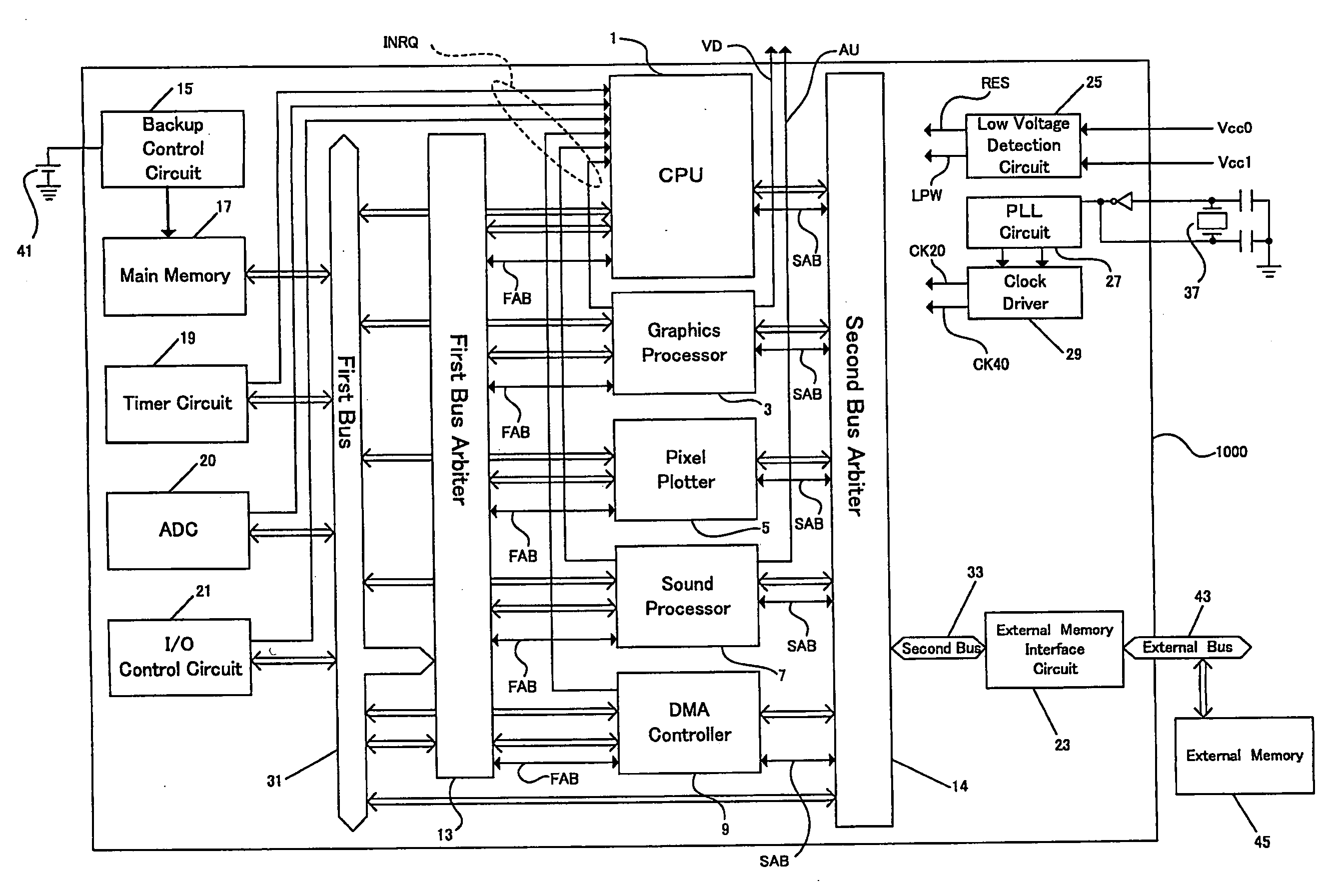
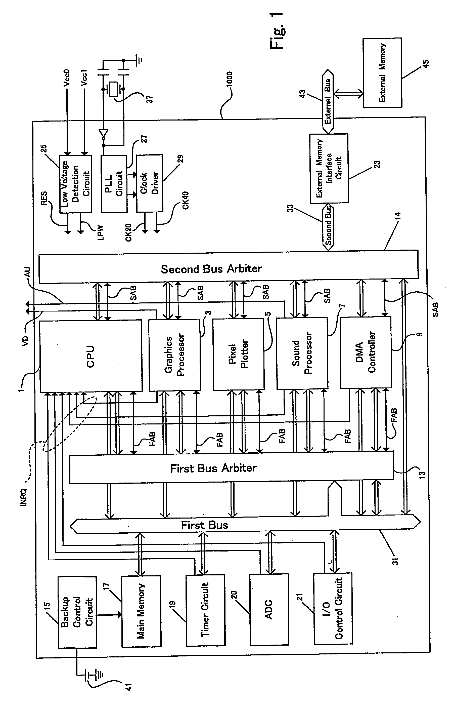
[0055]FIG. 1 is a block diagram showing the overall configuration of a processor 1000 as a data processing unit in accordance with an embodiment of the present invention. As shown in FI...


PUM


Abstract

An image mixing apparatus and a pixel mixer capable of mixing image data items having different pixel resolutions, and mixing image data items in an arbitrary display priority, irrespective of the order of mixing, even if the order of mixing is determined in advance is provided. Of two pixel data items having depth values “Zc” and “Zb”, one pixel data item having the depth value indicating that the pixel is located in a foreground position is selected by a pixel selection determination circuit 110. However, if a pixel data item has a hue indicating that the pixel is transparent, such a pixel data item is not selected but another pixel data item is selected instead. Multiplexers 112 to 116 output a pixel data item (hue “Hm”/color saturation “Sm”/brightness “Lm”) which is selected by the pixel selection determination circuit 110. Since pixel data items are input to the multiplexer 112 to 116 at different output rates, it is possible to mix images having different pixel resolutions.

Description

TECHNICAL FIELD[0001]The present invention relates to an image mixing apparatus and a pixel mixer for mixing a plurality of image data items on a display screen in real time.BACKGROUND ART[0002]FIG. 18 is an explanatory view for showing a prior art image processing system which has been disclosed in FIG. 11 of Japanese Patent Published Application No. Hei 7-104733. As shown in FIG. 18, an external device 550 outputs image data 590, priority information 600 indicative of whether the image data 590 is located over or under image data 620 of an external device 560, and information 610 indicative of whether the respective pixels of the image data 590 are transparent or not transparent. On the other hand, the external device 560 outputs the image data 620 and information 630 indicative of whether the respective pixels of the image data 620 are transparent or not transparent.[0003]On the basis of the priority information 600 and the information 610 and 630 indicative of whether or not the...

Claims


Application Information

Patent Timeline
IPC IPC(8): G06T1/00
CPCG09G5/001G09G5/395H04N5/265G09G2340/12H04N1/387G09G2340/10G06T3/00G09G5/36
Inventor KATO, SHUHEISANO, KOICHIUSAMI, KOICHI
Owner SHINSEDAI KK
Why Eureka
Try Eureka