Method and Device for Reducing the Fixed Pattern Noise of a Digital Image

a technology of fixed pattern noise and digital image, which is applied in the field of digital image fixed pattern noise reduction, can solve the problems of reducing image quality, reducing image quality, and not taking into account the third portion of pixel charge, so as to reduce degradation and reduce the fixed pattern noise of digital imag

Inactive Publication Date: 2009-08-27
PSIP LLC
View PDF105 Cites 73 Cited by
  • Summary
  • Abstract
  • Description
  • Claims
  • Application Information

AI Technical Summary

Benefits of technology

[0009]In one embodiment, a baseline FPN is determined from a dark image or an image taken under a given light condition either periodically or initially at the manufacturer. Then the “actual” FPN is determined based on the baseline FPN and on one or more of the “relevant variables,” which are defined as the variables that affect the FPN level of the area or pixel. These relevant variables include, but are not limited to, the brightness and color composition of the area or pixel, the operating temperature, the imaging sensor's voltage level and the gain of the image. The “actual” FPN is then subtracted from the area's image signals or the pixel's image signal. This results in an improved image with reduced degradation in the bright areas of the image. This may be done for every frame or a selected number of frames in the case of a video image signal.
[0010]According to one aspect of the invention, a method for reducing a digital image's fixed pattern noise includes determining the amount of FPN in a digital image taken by a digital imaging device as a function of at least one of brightness level, operating temperature, and gain value of the image on an area-by-area basis or on a pixel-by-pixel basis; and modifying the digital image by the determined amount of FPN on an area-by-area basis or on a pixel-by-pixel basis.

Problems solved by technology

The second and third portions of the pixel charges distort the true image signals and give rise to fixed pattern noise (FPN) in the image.
FPN appears as snow-like dots on a captured image and reduces the image's quality.
However, this method does not take into consideration the third portion of the pixel charge.
Therefore, this conventional method of using “dark image” data to cancel FPN produces the effect that the brighter areas of the image with low levels of FPN are overcompensated, resulting in the degradation of the image in those areas.
Although the FPN in the dark areas is adequately compensated by conventional FPN reduction methods, bright areas of the image tend to have low levels of FPN and are overcompensated by conventional FPN reduction methods, resulting in a degradation of the image in the bright areas.

Method used


Image

  • Method and Device for Reducing the Fixed Pattern Noise of a Digital Image
  • Method and Device for Reducing the Fixed Pattern Noise of a Digital Image
  • Method and Device for Reducing the Fixed Pattern Noise of a Digital Image

Examples


Embodiment Construction

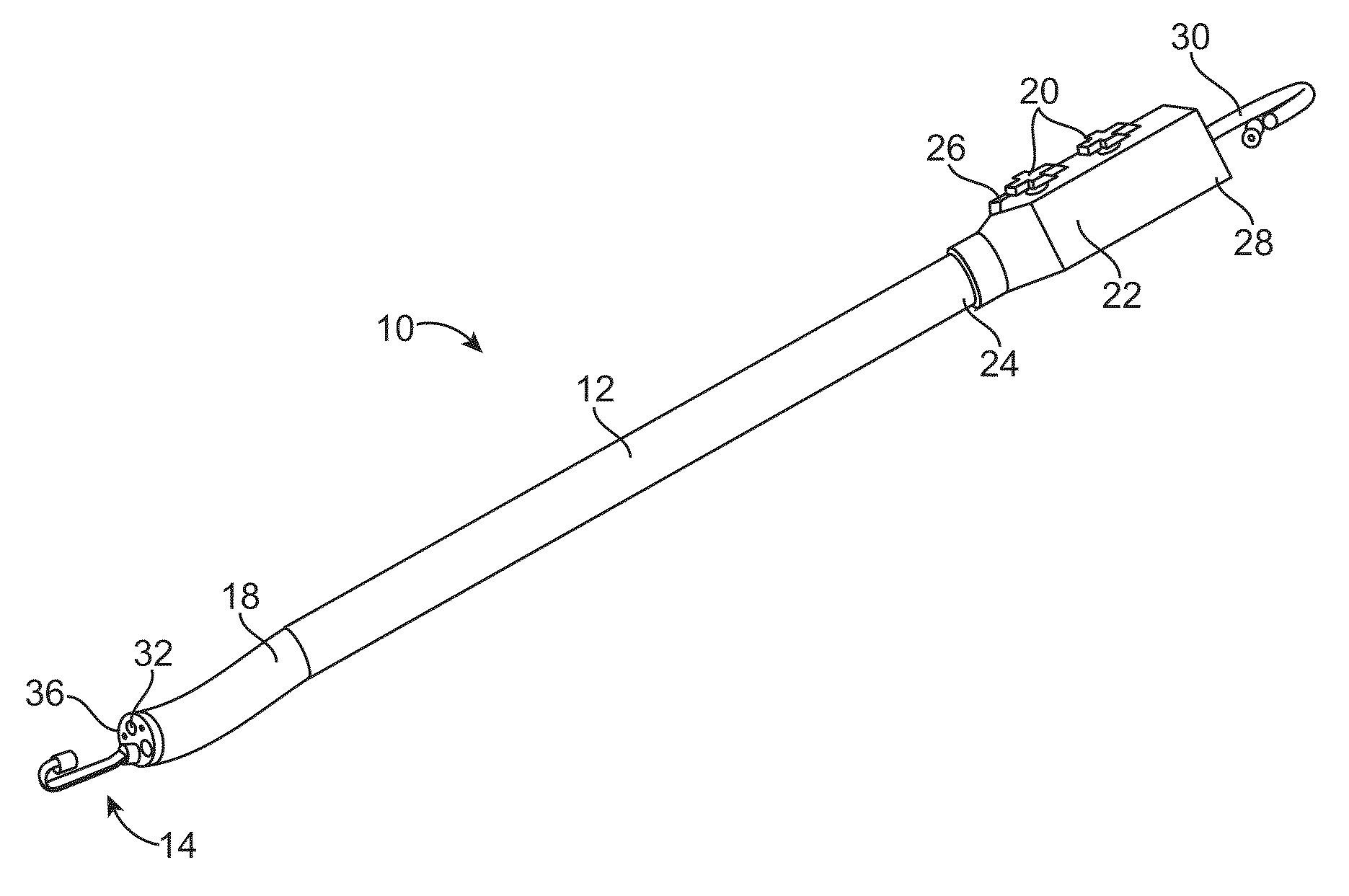
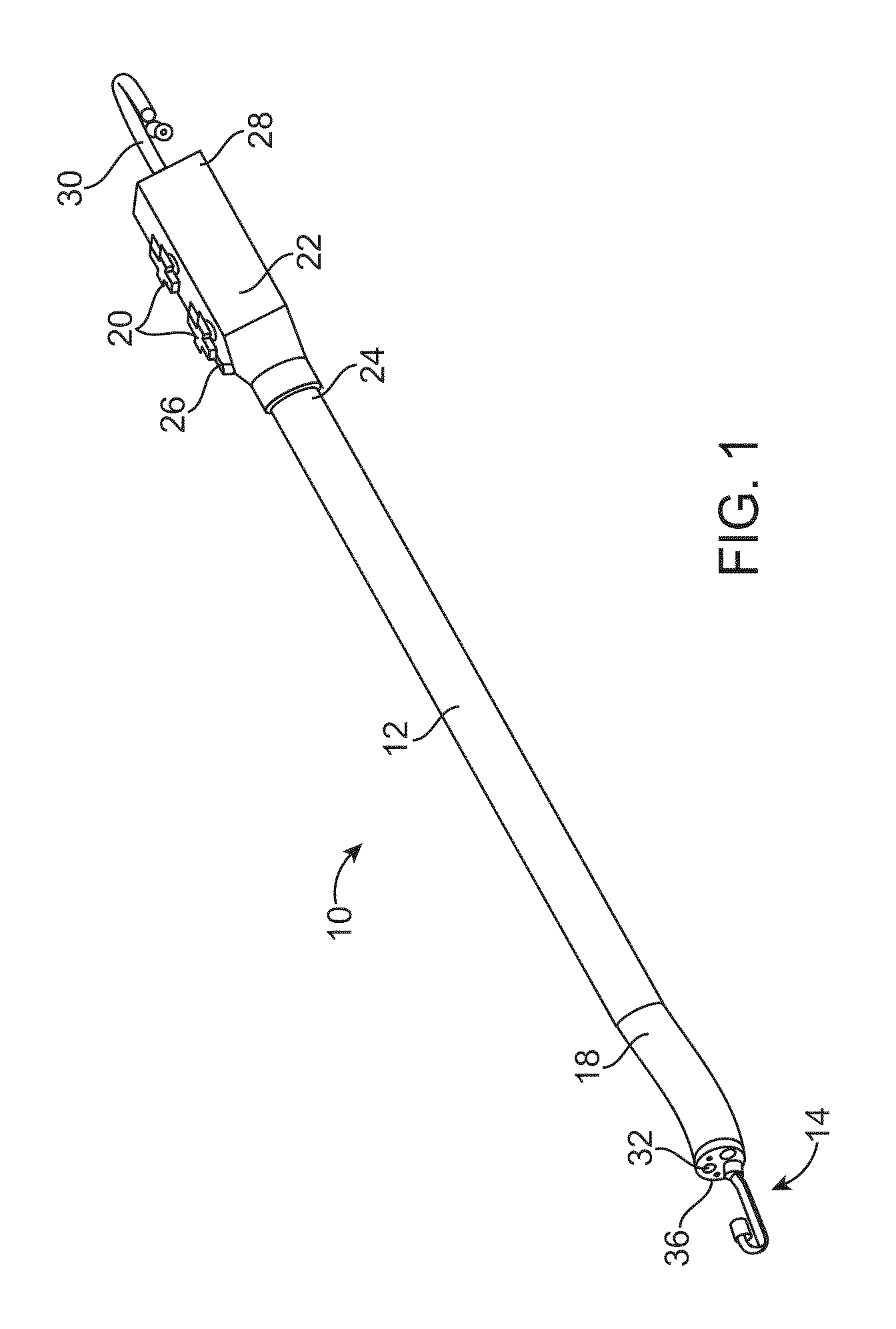
[0051]FIG. 1 illustrates an exemplary endoscope 10 of the present invention. This endoscope 10 can be used in a variety of medical procedures in which imaging of a body tissue, organ, cavity or lumen is required. The types of procedures include, for example, anoscopy, arthroscopy, bronchoscopy, colonoscopy, cystoscopy, EGD, laparoscopy, and sigmoidoscopy.

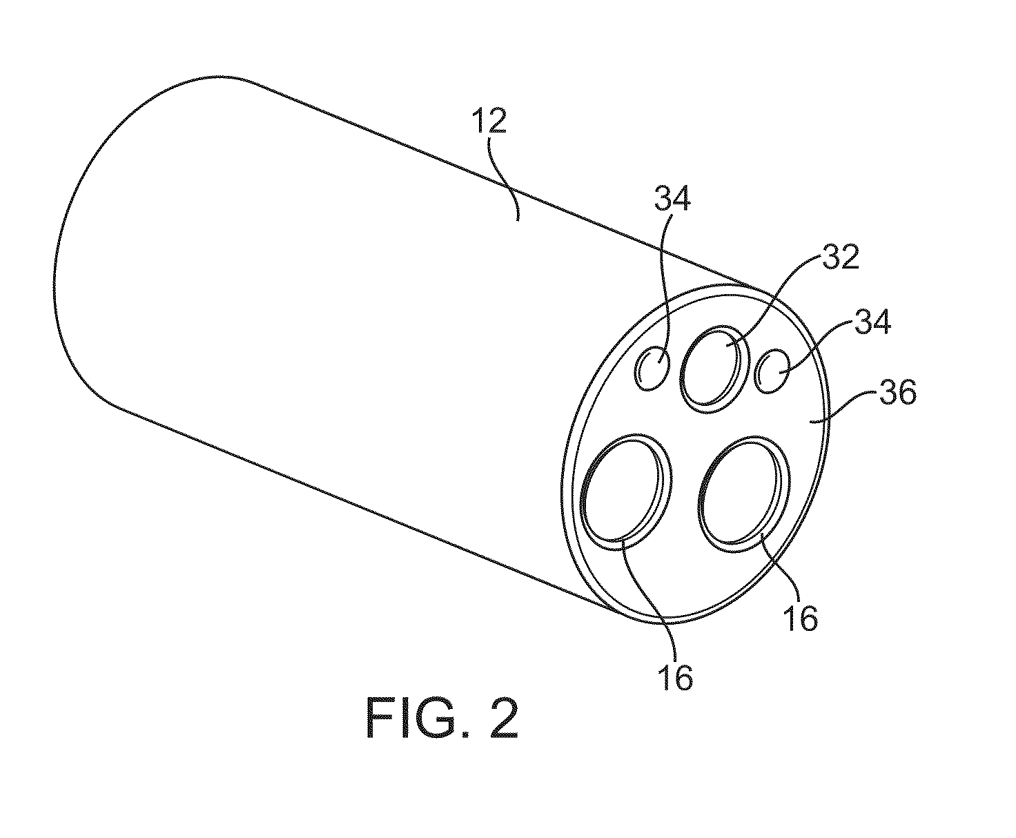
[0052]The endoscope 10 of FIG. 1 includes an insertion tube 12 and an imaging assembly 14, a section of which is housed inside the insertion tube 12. As shown in FIG. 2, the insertion tube 12 has two longitudinal channels 16. In general, however, the insertion tube 12 may have any number of longitudinal channels. An instrument can reach the body cavity through one of the channels 16 to perform any desired procedures, such as to take samples of suspicious tissues or to perform other surgical procedures such as polypectomy. The instruments may be, for example, a retractable needle for drug injection, hydraulically actuated scissors, c...


PUM


Abstract

A method or a device that reduces fixed pattern noise in an image captured by a digital image device and adjusts the reduction based on the level of FPN, preferably on an area-by-area basis or on a pixel-by-pixel basis.

Description

[0001]This application claims the benefit of U.S. Provisional Patent Application No. 60 / 979,368, filed Oct. 11, 2007, the entire disclosure of which is incorporated herein by reference.FIELD OF THE INVENTION[0002]The present invention relates to a method for reducing the fixed pattern noise of a digital image and a device for reducing the fixed pattern noise of a digital image.BACKGROUND OF THE INVENTION[0003]Digital imaging devices have a variety of applications. For example, they are used in endoscopic devices for medical procedures or for inspecting small pipes or for remote monitoring. One example of such endoscopic devices is an endoscope having a retrograde-viewing auxiliary imaging device, which is being developed by Avantis Medical Systems, Inc. of Sunnyvale, Calif.[0004]There are various types of digital imaging devices. On example is a digital imaging device using complementary metal oxide semiconductor (CMOS) technology. During operation, each pixel of the device generate...

Claims


Application Information

Patent Timeline
Patent Type & Authority Applications(United States)
IPC IPC(8): H04N7/18G06K9/40H04N5/217H04N5/76
CPCA61B1/00181A61B1/05H04N5/217H04N5/2256H04N2005/2255H04N5/23229H04N5/361H04N5/3651H04N5/2258H04N23/81H04N23/56H04N23/555H04N23/45H04N23/80H04N25/671H04N25/63
Inventor BAYER, LEXSTEWART, MICHAEL
Owner PSIP LLC
Why Eureka
Try Eureka