Method and apparatus of providing synchronous regulation circuit for offline power converter

a technology of offline power converter and synchronous regulation circuit, which is applied in the direction of dc-dc conversion, power conversion system, climate sustainability, etc., can solve the problems of low efficiency at light load, foregoing power converter, low efficiency, etc., and achieve the effect of improving the efficiency of offline power converter

Active Publication Date: 2009-08-27
SEMICON COMPONENTS IND LLC
View PDF12 Cites 59 Cited by
  • Summary
  • Abstract
  • Description
  • Claims
  • Application Information

AI Technical Summary

Benefits of technology

[0005]Synchronous regulation methods, synchronous regulation circuits and power converters are provided. An exemplary embodiment of a synchronous regulation circuit is developed to improve the efficiency of offline power converter. It includes a primary-side switching circuit, a secondary-side switching circuit, a synchronous switch and a flyback switch. The secondary-side switching circuit is coupled to the output of the power converter to generate a pulse signal and a synchronous signal in response to an oscillation signal and a feedback signal. The feedback signal is correlated to the output of the power converter. The synchronous signal is coupled from the secondary side of the power converter to the primary side of the power converter through an isolation device. The primary-side switching circuit generates a switching signal in response to the synchronous signa

Problems solved by technology

The drawback of foregoing power converters is low efficiency at light load.
An insufficient circular power causes hard switching and results low ef

Method used


Image

  • Method and apparatus of providing synchronous regulation circuit for offline power converter
  • Method and apparatus of providing synchronous regulation circuit for offline power converter
  • Method and apparatus of providing synchronous regulation circuit for offline power converter

Examples


Embodiment Construction

[0026]The following description is of the best-contemplated mode of carrying out the invention. This description is made for the purpose of illustrating the general principles of the invention and should not be taken in a limiting sense. The scope of the invention is best determined by reference to the appended claims.

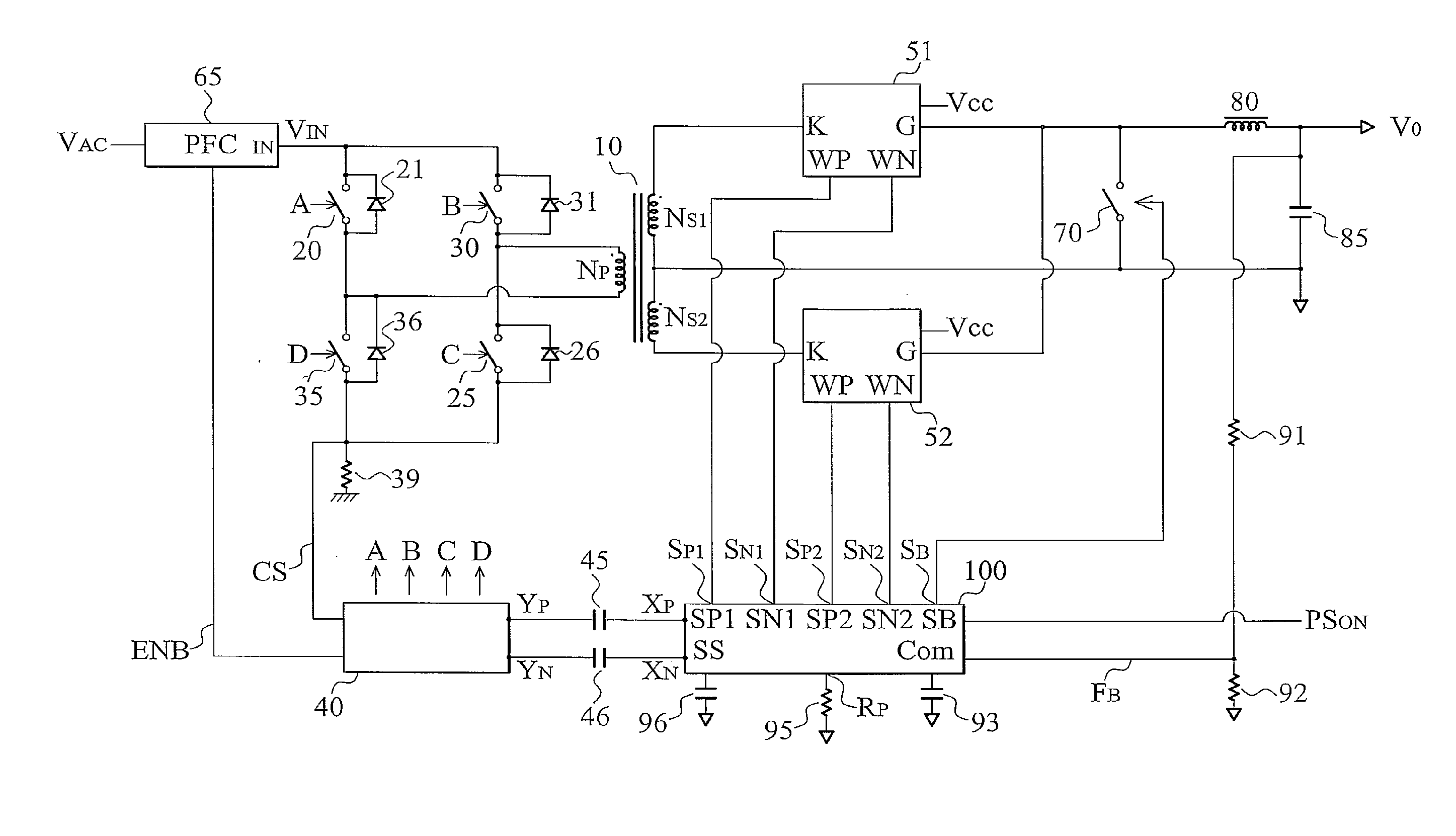
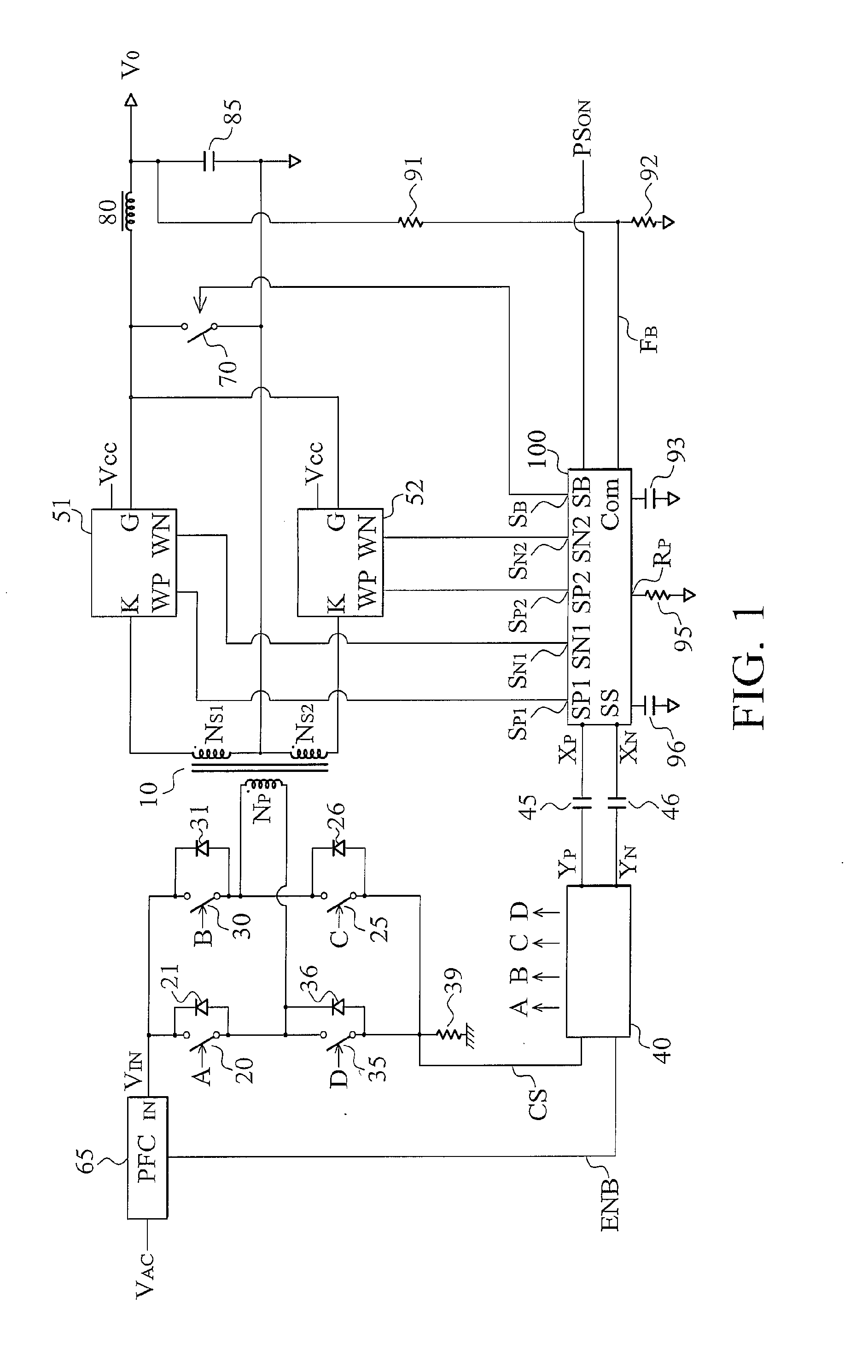
[0027]FIG. 1 shows an offline power converter with synchronous regulation circuit according to an embodiment of the invention. The power converter includes a transformer 10 having a primary side and a secondary side. At the primary side, a primary winding NP of the transformer 10 is connected to four power switches 20, 25, 30, and 35 for switching the transformer 10. A primary-side switching circuit 40 generates switching signals A, B, C, and D in response to synchronous signals YP and YN. Switching signals A, B, C, and D are coupled to switch the primary winding NP of the transformer 10. The primary-side switching circuit 40 further generates an enable signal ENB coup...


PUM


Abstract

A synchronous regulation circuit is provided. A secondary-side switching circuit is coupled to the output of the power converter to generate a synchronous signal and a pulse signal in response to an oscillation signal and a feedback signal. An isolation device transfers the synchronous signal from the secondary side to the primary side of the power converter. A primary-side switching circuit receives the synchronous signal to generate a switching signal for soft switching a transformer. The pulse signal is utilized to control a synchronous switch for rectifying and regulating the power converter. The synchronous switch includes a power switch and a control circuit. The control circuit receives the pulse signal for turning on or off the power switch. The power switch is connected between the transformer and the output of the power converter. A flyback switch is operated as a synchronous rectifier to freewheel the inductor current of the power converter. The flyback switch is turned on in response to the off state of the power switch. The turn-on period of flyback switch is correlated to the turn-on period of the power switch.

Description

BACKGROUND OF THE INVENTION[0001]1. Field of the Invention[0002]The invention relates to power converters, and more particularly to synchronous power converter of power converters.[0003]2. Description of the Related Art[0004]An offline power converter includes a power transformer to provide isolation from an AC line input to the output of the power converter for safety. In recent development, using soft switching topologies in the primary side of the transformer and applying the synchronous rectifier in the secondary side of the transformer are to reach a higher efficiency for power conversion. Among them, the full-bridge quasi-resonant ZVS techniques are described in “Constant frequency resonant power converter with zero voltage switching” by Christopher, P. Henze, et al, U.S. Pat. No. 4,855,888; “Soft-switching PWM converters” by Guichao C. Hua and Fred C. Lee, U.S. Pat. No. 5,442,540; “Zero switching power converter operable as asymmetrical full-bridge converter” by Yang, et al, ...

Claims


Application Information

Patent Timeline
IPC IPC(8): H02M1/00H02M7/00H02M7/217
CPCH02M3/33507Y02B70/1475H02M3/33592H02M3/33523Y02B70/10
Inventor YANG, TA-YUNG
Owner SEMICON COMPONENTS IND LLC
Why Eureka
Try Eureka