Monitor circuit for monitoring property of optical fiber transmission line and quality of optical signal

a technology of optical fiber transmission line and monitoring circuit, which is applied in the direction of optical apparatus testing, transmission monitoring, instruments, etc., can solve the problems of affecting the downsizing and/or cost-cutting of optical receivers, and possible heavy damag

Inactive Publication Date: 2009-08-27
FUJITSU LTD
View PDF14 Cites 53 Cited by
  • Summary
  • Abstract
  • Description
  • Claims
  • Application Information

AI Technical Summary

Benefits of technology

[0008]An object of the embodiments is to downsize and / or cost-cut a monitor circuit for monitoring a property of an optical fiber transmission line and the quality of an optical signal.

Problems solved by technology

Therefore, heavy damage may possibly occur if the data transmission is halted.
Accordingly, a plurality of monitor devices must be implemented to monitor a plurality of types of properties, leading to an obstacle to the downsizing and / or the cost-cutting of an optical receiver.

Method used


Image

  • Monitor circuit for monitoring property of optical fiber transmission line and quality of optical signal
  • Monitor circuit for monitoring property of optical fiber transmission line and quality of optical signal
  • Monitor circuit for monitoring property of optical fiber transmission line and quality of optical signal

Examples


first embodiment

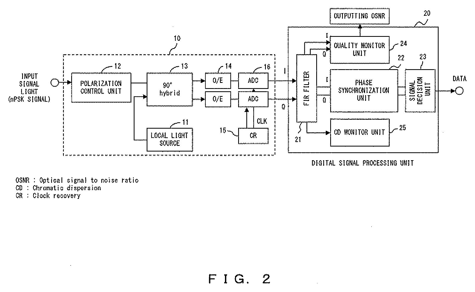
[0047]FIG. 2 is a block diagram illustrating a configuration of an optical receiver including a monitor circuit according to a first embodiment. This optical receiver is configured by including an optical reception circuit 10 for making coherent reception of an optical signal, and a digital signal processing unit (DSP) 20 provided at a stage succeeding the optical reception circuit 10. The monitor circuit is implemented with the digital signal processing unit 20 and this will be described in detail later. Here, assume that an input optical signal is an optical mPSK signal.

[0048]The optical reception circuit 10 includes a local light source 11, a polarization control unit 12, an optical hybrid unit 13, photo reception units 14, a clock recovery unit 15, and A / D converters 16. The local light source 11 generates a local light with almost the same frequency as that of an input light. The local light is, for example, continuous wave light. The polarization control unit 12 controls the p...

second embodiment

[0066]FIG. 7 is a block diagram illustrating a configuration of an optical receiver including a monitor circuit according to a second embodiment. The basic configuration of the monitor circuit according to the second embodiment is the same as the first embodiment illustrated in FIG. 2. Note that, however, a configuration and operations of a quality monitor unit 41 included in the monitor circuit according to the second embodiment are different from those of the quality monitor unit 24 in the first embodiment.

[0067]The quality monitor unit 41 includes a filter 42 and a power computing unit 43. The filter 42 is an LPF (Low Pass Filter) or a BPF (Band Pass Filter), and implemented, for example, with an FIR filter. If the filter 42 is implemented with an LPF, a cutoff frequency is set to, for example, about “0.6×fsig”. “fsig” is the symbol rate of data transmitted by the optical signal. The BPF is designed to transmit a predetermined bandwidth on the low frequency side of “fsig”.

[0068]F...

third embodiment

[0073]FIG. 11 is a block diagram illustrating a configuration of an optical receiver including a monitor circuit according to a third embodiment. The basic configuration of the monitor circuit according to the third embodiment is the same as the first embodiment illustrated in FIG. 2. Note that, however, a configuration and operations of a quality monitor unit 51 included in the monitor circuit according to the third embodiment are different from those of the quality monitor unit 24 in the first embodiment.

[0074]The quality monitor unit 51 receives the electric field data of an optical signal after being synchronized, the frequency offset of which is compensated and the phase error of which is removed by the phase synchronization unit 22. Then, the quality monitor unit 51 calculates a quality index Fquality on the basis of the optical electric field data after being phase-synchronized.

[0075]FIG. 12 is a flowchart illustrating the procedure for calculating the quality of an optical s...


PUM


Abstract

An optical reception circuit generates optical electric field data by performing coherent reception of an optical signal transmitted via an optical fiber transmission line. An FIR filter filters the optical electric field data so that the optical signal is equalized. A quality monitor unit calculates the average value and the standard deviation value of the amplitude of the optical signal on the basis of the equalized optical electric field data, and further calculates an optical signal-to-noise ratio on the basis of the calculated values.

Description

BACKGROUND [0001]1. Field[0002]The present invention relates to a monitor method and a monitor circuit for monitoring a property of an optical fiber transmission line and the quality of an optical signal transmitted via the optical fiber transmission line, and to an optical receiver including the monitor circuit.[0003]2. Description of the Related Art[0004]An optical communications system using an optical fiber transmission line generally offers a high-speed data transmission, by which an enormous amount of information is transmitted / received. Therefore, heavy damage may possibly occur if the data transmission is halted. Accordingly, methods for monitoring the property of an optical transmission line or the quality of an optical signal are proposed. Monitoring an optical transmission line and an optical signal is effective also at efficiently operating an optical communications system.[0005]Patent Document 1 (Japanese Patent Publication No. 2001-194267) recites the method for evalua...

Claims


Application Information

Patent Timeline
Patent Type & Authority Applications(United States)
IPC IPC(8): H04B10/08G01M11/00G01M11/02H04B10/07H04B10/54H04B10/556H04B10/58
CPCH04B10/6971H04B10/0795
Inventor ODA, SHOICHIROHOSHIDA, TAKESHINAKASHIMA, HISAOTANIMURA, TAKAHITO
Owner FUJITSU LTD
Why Eureka
Try Eureka