Method for reducing surface defects on patterned resist features

Inactive Publication Date: 2009-08-27
TOKYO ELECTRON LTD
View PDF9 Cites 34 Cited by
  • Summary
  • Abstract
  • Description
  • Claims
  • Application Information

AI Technical Summary

Benefits of technology

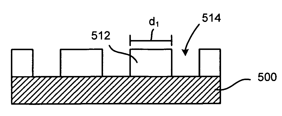
[0006]The method includes providing a substrate with a patterned resist feature containing surface defects with convex and concave regions, applying an acid solution to the patterned resist feature to form a surface acid layer on the patterned resist feature, heat-treating the patterned resist feature, where the heat-treating causes acid concentration in the convex regions and acid dispersion in the concave regions, an

Problems solved by technology

As the drive toward smaller and smaller features continues, several new problems in the manufacture of these very small features are becoming visible.
One problem is called line edge roughness (LER).
In the smallest features being formed, the

Method used


Image

  • Method for reducing surface defects on patterned resist features
  • Method for reducing surface defects on patterned resist features
  • Method for reducing surface defects on patterned resist features

Examples


Embodiment Construction

[0019]Embodiments of the invention provide a method for post-processing lithographically patterned resists to reduce surface defects in a patterned resist feature. One skilled in the relevant art will recognize that the various embodiments may be practiced without one or more of the specific details, or with other replacement and / or additional methods, materials, or components. In other instances, well-known structures, materials, or operations are not shown or described in detail to avoid obscuring aspects of various embodiments of the invention. Similarly, for purposes of explanation, specific numbers, materials, and configurations are set forth in order to provide a thorough understanding of the invention. Furthermore, it is understood that the various embodiments shown in the figures are illustrative representations and are not necessarily drawn to scale.

[0020]Reference throughout this specification to “one embodiment” or “an embodiment” means that a particular feature, structur...


PUM


Abstract

A method is provided for post-processing lithographically patterned resists to reduce surface defects on a patterned resist feature. The method includes providing a substrate with a patterned resist feature containing surface defects with convex and concave regions, applying an acid solution to the patterned resist feature to form a surface acid layer on the patterned resist feature, heat-treating the patterned resist feature, where the heat-treating causes acid concentration in the convex regions and acid dispersion in the concave regions. The method further includes exposing the heat-treated patterned resist feature to a developing solution to preferentially remove resist material from the convex regions and form a trimmed patterned resist feature with reduced surface defects. According to one embodiment, the method further includes repeating the applying, heat-treating, and exposing at least once to further trim and reduce surface defects on the trimmed patterned resist feature.

Description

FIELD OF THE INVENTION[0001]The invention is related to semiconductor processing, in particular, to methods for processing radiation sensitive material on a substrate (wafer).BACKGROUND OF THE INVENTION[0002]Lithographic processes using radiation sensitive material (also referred to herein as “resist”) are widely used in the manufacture of semiconductor devices and other patterned structures. In track photolithographic processing used in the fabrication of semiconductor devices, the following sorts of processes may be performed in sequence: photoresist coating that coats a photoresist solution on a semiconductor wafer to form a resist film, heat processing to cure the coated resist film, exposure processing to expose a predetermined pattern on the photoresist film, heat processing to promote a chemical reaction within the photoresist film after exposure, developing processing to develop the exposed photoresist film, etc.[0003]In a photolithographic process, the photoresist can be ex...

Claims


Application Information

Patent Timeline
IPC IPC(8): G03F7/26H01L21/306
CPCG03F7/40H01L21/6708H01L21/0273
Inventor KULP, JOHN M.
Owner TOKYO ELECTRON LTD
Why Eureka
Try Eureka