Integrated chemical mechanical polishing composition and process for single platen processing
a technology of chemical mechanical polishing composition and processing process, which is applied in the direction of lapping machines, other chemical processes, manufacturing tools, etc., can solve the problems of defectivity and polish performance degradation
- Summary
- Abstract
- Description
- Claims
- Application Information
AI Technical Summary
Benefits of technology
Problems solved by technology
Method used
Image
Examples
example 1
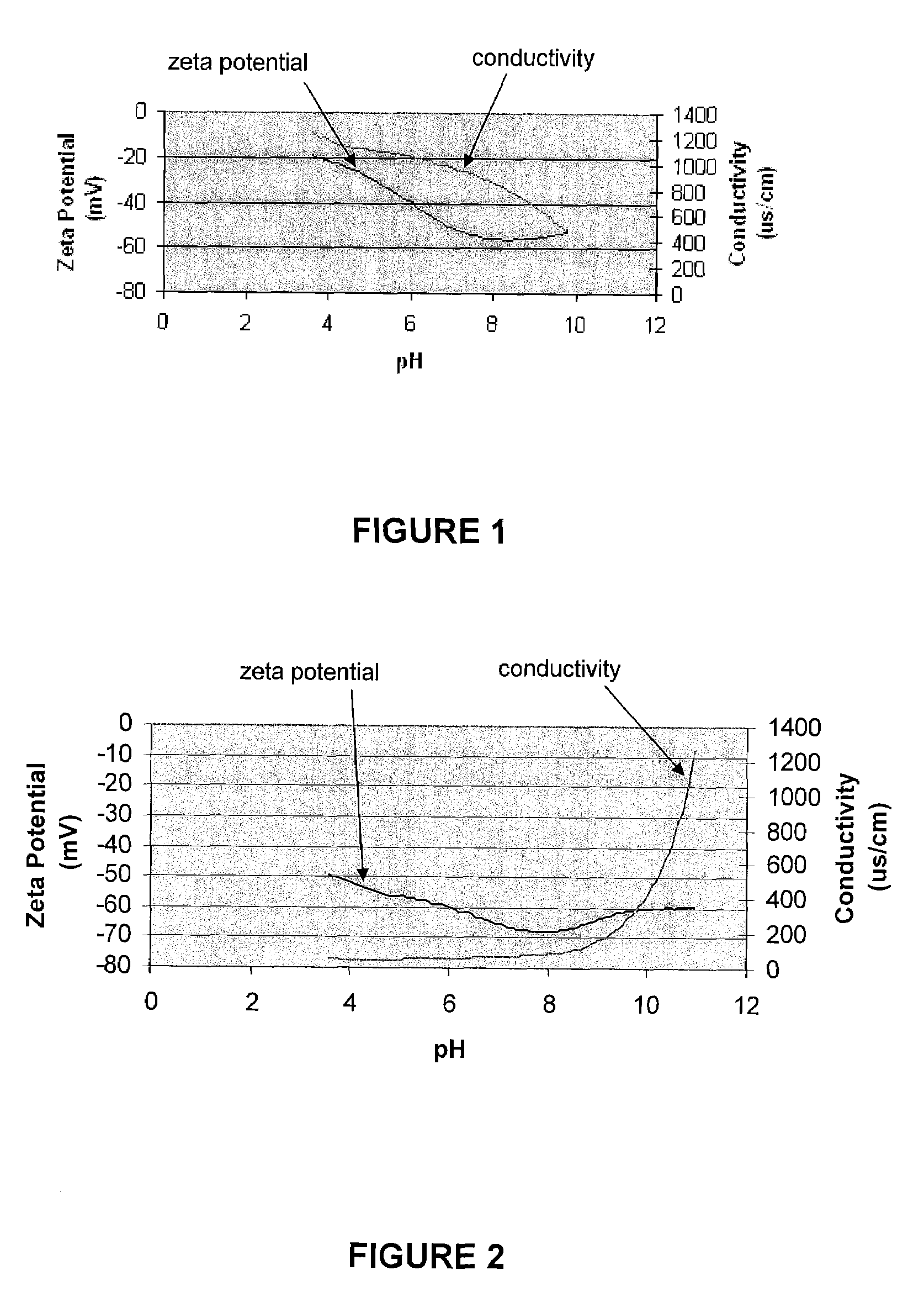
[0096]As introduced hereinabove, preferably, the abrasive component of the present invention is stable in acidic media, for example an acid-stable colloidal silica having a zeta potential less than about −50 mV, i.e., more negative, in a pH range of 4 and above. Comparing FIGS. 1 and 2, which correspond to a standard 3.1 wt. % ATMI OS70KL™ 70 nm silica aqueous slurry and a 4 wt. % acid-stable silica aqueous slurry, respectively, it can be seen that the acid-stable silica slurry is highly negative throughout the pH range, which ensures better colloidal stability, i.e., the charged particles repel one another and thus overcome the natural tendency to aggregate. Moreover, the stability in the acidic range ensures pH compatibility between the liquid components of the slurry and the abrasive.
example 2
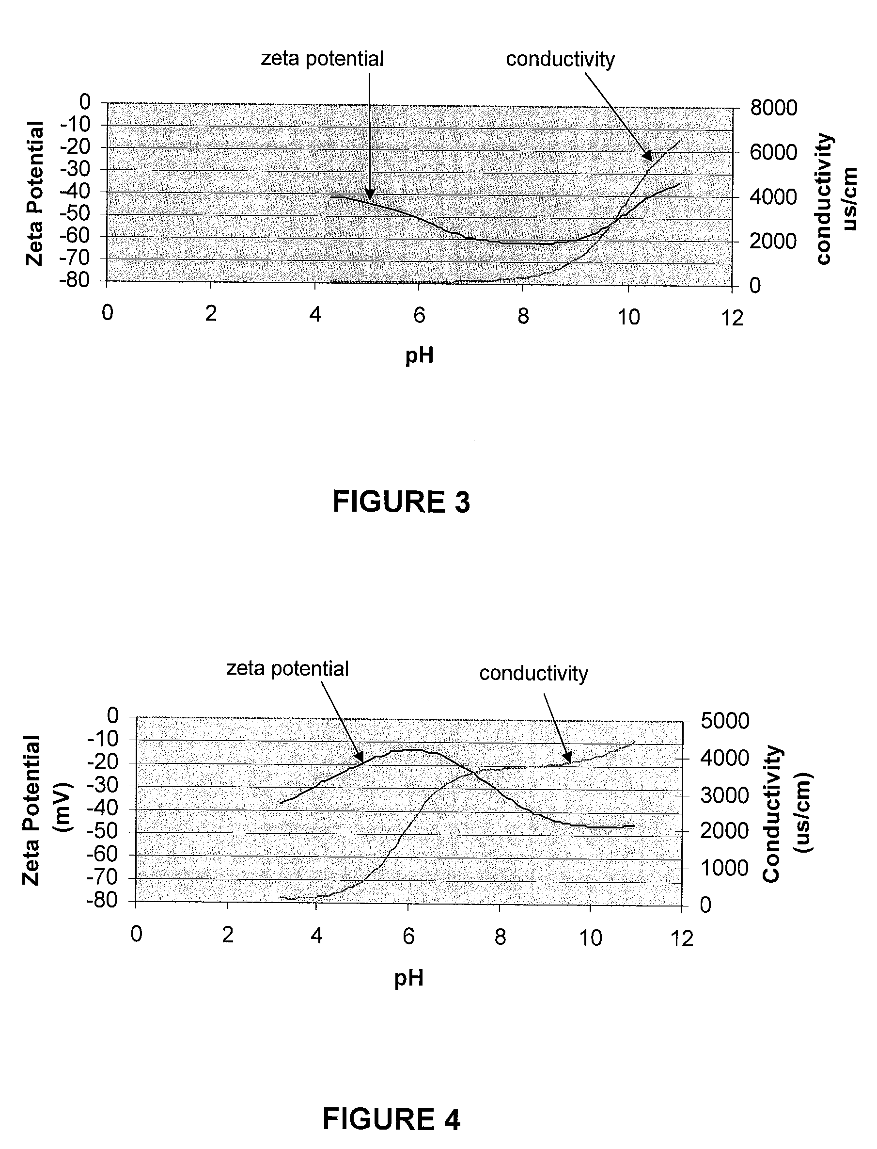
[0097]FIG. 3 illustrates the potentiometric titration of an aqueous slurry including 4 wt. % acid-stable silica and 0.4 wt. % 1,2,4-triazole passivating agent. Importantly, the zeta potential throughout the pH range remains substantially negatively charged, similar to that of the silica in the absence of the passivating agent (see, e.g., FIG. 2), which indicates negligible interaction between the abrasive and the passivating agent. By way of illustration, FIG. 4 represents an experiment where substantial interaction between the abrasive and the passivating agent was observed. FIG. 4 illustrates the electrostatic potential of an aqueous slurry including 4 wt. % acid-stable silica and 0.4 wt. % 5-amino, 1H-tetrazole passivating agent. Comparing the zeta potential curve of FIG. 4 with that of FIG. 2 (i.e., the acid-stable silica in the absence of passivating agent), it can be seen that the curves are distinctly different in shape over the pH range. This distinct difference in electrost...
example 3
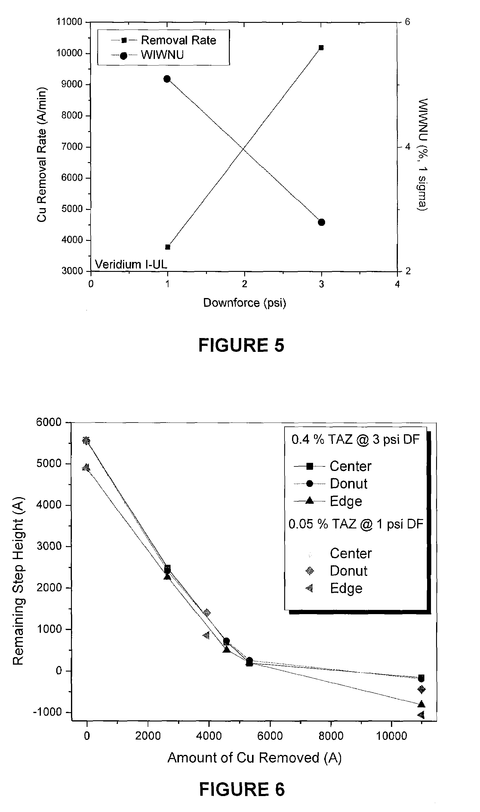
[0098]Referring to FIGS. 5 and 6, the planarization efficiency using Formulations A and B is illustrated. FIG. 5 illustrates the removal rate of Cu, in Å min−1, and the WIWNU as a function of downforce using the Step I CMP formulation B. It can be seen that the removal rate of copper is high and the WIWNU is low, which corresponds to the preferred results during Step I Cu planarization processes. Further, referring to FIG. 6, it can be seen that formulation B has about the same planarization efficiency at one-third the downforce pressure as formulation A.
PUM
| Property | Measurement | Unit |
|---|---|---|
| zeta potential | aaaaa | aaaaa |
| particulate diameter | aaaaa | aaaaa |
| particulate diameter | aaaaa | aaaaa |
Abstract
Description
Claims
Application Information
 - R&D
- Intellectual Property
- Life Sciences
- Materials
- Tech Scout
- Unparalleled Data Quality
- Higher Quality Content
- 60% Fewer Hallucinations
Browse by: Latest US Patents, China's latest patents, Technical Efficacy Thesaurus, Application Domain, Technology Topic, Popular Technical Reports.
© 2025 PatSnap. All rights reserved.Legal|Privacy policy|Modern Slavery Act Transparency Statement|Sitemap|About US| Contact US: help@patsnap.com


