Surgical insertion device for use in orthopedic surgery

a surgical and orthopedic technology, applied in the field of surgical insertion devices for use in orthopedic surgery, can solve the problems of difficult entry of surgeons into the cup liner, time-consuming and difficult tasks, and the problem of difficult to remove the cup liner

Inactive Publication Date: 2009-08-27
SURGICAL INSTR SERVICE
View PDF4 Cites 24 Cited by
  • Summary
  • Abstract
  • Description
  • Claims
  • Application Information

AI Technical Summary

Benefits of technology

[0006]The objects mentioned above, as well as other objects, are solved by the present invention, which overcomes disadvantages of prior insertion devices and methods used for locating prosthetic cups in the hip cup socket, while providing new advantages not previously associated with such devices and methods.
[0009]Following coupling of the engaging mechanism to the cup liner, and seating of the cup liner within the cup, the engaging mechanism may be retracted in a proximal direction relative to the main body, thereby dislodging the engaging mechanism from the liner seat, preferably in a substantially wobble-free manner, without dislodging the cup liner from its seating within the cup. To enable extension or retraction of the engaging mechanism relative to the main body, a portion of the main body may include a slot, and a slide handle may be positioned outside the main body and movable along the slot. In this embodiment, movement of the slide handle enables the engaging mechanism to move distally or proximally relative to the main body of the device.
[0010]In a preferred embodiment, the main body has a main axis, and the engaging mechanism moves along an engaging axis, and the main and engaging axes are not substantially aligned, and preferably form a substantial angle between them, such as 30-60 degrees, and most preferably about 45 degrees, to provide the instrument user with a direct view of the surgical site (i.e., with such a substantial angle, the main body will not impair the viewpoint from the proximal end of the device to the distal end of the device).
[0011]The proximal end of the device may be connected to the engaging mechanism using various mechanisms, such as a wire rope located within the main body and traveling along the main and engaging axes. A liner having a smooth inner surface may surround at least a portion of the wire rope, for example, to keep it from kinking during its movement along the bent or elbow portion of the preferred device.

Problems solved by technology

In practice, properly orienting and locating the cup liner within the cup covering the acetabulum of the hip bone, and then decoupling the cup liner from the insertion device, have proven to be problematic and time-consuming tasks.
Even if the surgical team has appropriately sized the cup liner, if the cup liner is not located exactly correctly within the cup, it will need to be removed and re-located; cup liner removal can be problematic, as seen by FIG. 6A, as the cup liner can get wedged and stuck within the cup at an improper orientation.
Many patients have a substantial amount of tissue (depth) between the implanted cup and the skin surface and it is difficult for the surgeon to gain entry to the cup liner.
In practice, during surgery, it can take as long as 45 minutes to dislodge the cup liner.
Such prior insertion devices did not resolve the problematic issues of adequately engaging the cup liner, aligning the liner with the cup, and releasing the liner from a proximal release point.

Method used


Image

  • Surgical insertion device for use in orthopedic surgery
  • Surgical insertion device for use in orthopedic surgery
  • Surgical insertion device for use in orthopedic surgery

Examples


Embodiment Construction

[0025]Set forth below is a description of what are currently believed to be the preferred embodiments and / or best examples of the invention claimed. Future and present alternatives and modifications to these preferred embodiments are contemplated. Any alternatives or modifications which make insubstantial changes in function, in purpose, in structure or in result are intended to be covered by the claims of this patent.

[0026]Below, “SIS” refers to Surgical Instrument Service Company of Carol Stream, Ill. “McMaster” refers to McMaster-Carr of Chicago, Ill. “Atlas Fibre” refers to Atlas Fibre Company of Skokie, Ill.

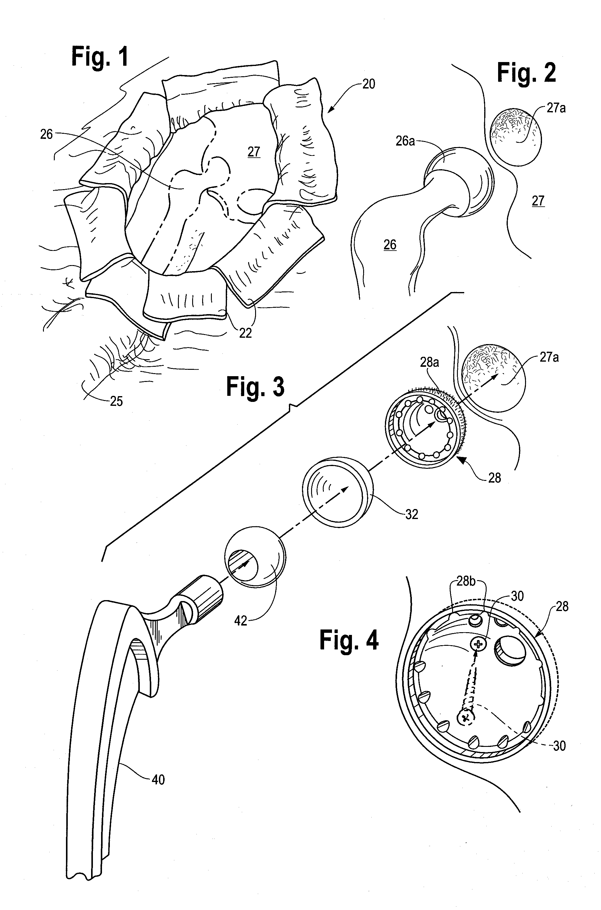
[0027]Referring first to FIGS. 1-2, a hip replacement surgical site, designated generally as 20 is shown, with retracted skin flaps 22, the femoral portion 25 of a leg, and the hip / pelvic bone portion 27. The upper portion of the femur bone 26 terminates in a ball portion 26a which attaches to the socket 27a of hip bone portion 27, as shown in FIG. 2.

[0028]To provide an over...


PUM


Abstract

A device, and a method for using it, for implanting a cup liner within a cup attached to the acetabulum of the hip bone, during hip replacement surgery. In a preferred embodiment, the device includes a main body with proximal and distal ends. The distal end may terminate in a liner seat and an engaging mechanism. Initially, the engaging mechanism may be coupled to the cup liner; a slight retraction of the engaging mechanism relative to the main body and liner seat may be sufficient to properly seat the cup liner on the liner seat. The device is now used to place the cup liner within the cup. The engaging mechanism may again be retracted to disengage the cup liner from the engaging mechanism, without dislodging the cup liner from the cup.

Description

BACKGROUND OF THE INVENTION[0001]The present invention relates to an insertion device and method for facilitating hip replacement surgery. More specifically, the present relates to an insertion device and method for implanting a cup liner into a cup, which is itself seated within the acetabulum or cup socket of the hip / pelvic bone.[0002]With modem hip replacement surgery, in summary fashion, the hip / pelvic bone is disclocated from the femur bone, and the femoral head (ball joint) is removed from the top of the femur bone. The cup portion or “acetabulum” which forms the resulting, exposed socket of the upper portion of the hip bone is then reamed, removing and smoothing worn portions. A prosthetic, metal cup with a non-smooth surface to stimulate bone growth, is then located within the acetabulum, and fixed in position using one or more screws. A cup liner with a smooth inside, concave surface is then seated within the cup. After reaming the femur bone, a broach or metal stem is then...

Claims


Application Information

Patent Timeline
Patent Type & Authority Applications(United States)
IPC IPC(8): A61B17/58
CPCA61F2/34A61F2/4609A61F2/4637A61F2002/30566A61F2002/4627A61F2002/4685
Inventor POSDAL, GREGORY J.
Owner SURGICAL INSTR SERVICE
Why Eureka
Try Eureka