LNG Vapor Handling Configurations And Methods

a technology of lng vapor and configuration, applied in the direction of load accommodation, container discharge methods, lighting and heating apparatus, etc., can solve the problems of significant cost to the lng receiving terminal, large amount of lng vapor that must be further processed, and significant problems to maintain lng in the transfer line, so as to reduce the boil-off volume

Inactive Publication Date: 2009-09-03
FLUOR TECH CORP
View PDF14 Cites 24 Cited by
  • Summary
  • Abstract
  • Description
  • Claims
  • Application Information

AI Technical Summary

Benefits of technology

[0009]The present invention is directed to configurations and methods of LNG transfer from an LNG source to an LNG storage tank, where refrigeration content of compressed, condensed, and expanded boil-off from the LNG storage tank is employed to subcool the LNG stream in a position intermediate th

Problems solved by technology

Despite its apparent simplicity, LNG ship unloading poses various significant challenges in several economic and technical aspects.
Moreover, LNG unloading docks and LNG storage tanks are often separated by relatively large distances (e.g., as much as 3 to 5 miles), which frequently causes significant problems to maintain LNG in the transfer line at cryogenic temperatures (i.e., −255° F. and lower).
As a consequence, large amounts of LNG vapor are formed that must be further processed.
In such configurations, a dedicated vapor return line is required which adds significant cost to the LNG receiving terminal.
As relatively large volumes of vapor are handled by such compressors, currently known compression and vapor absorption systems require significant energy and operator attention, particularly during transition from normal holding operation to ship unloading operation.
During normal holding operation, the LNG transfer line generally remains stagnant, which leads to an increase in te

Method used


Image

  • LNG Vapor Handling Configurations And Methods
  • LNG Vapor Handling Configurations And Methods
  • LNG Vapor Handling Configurations And Methods

Examples


Embodiment Construction

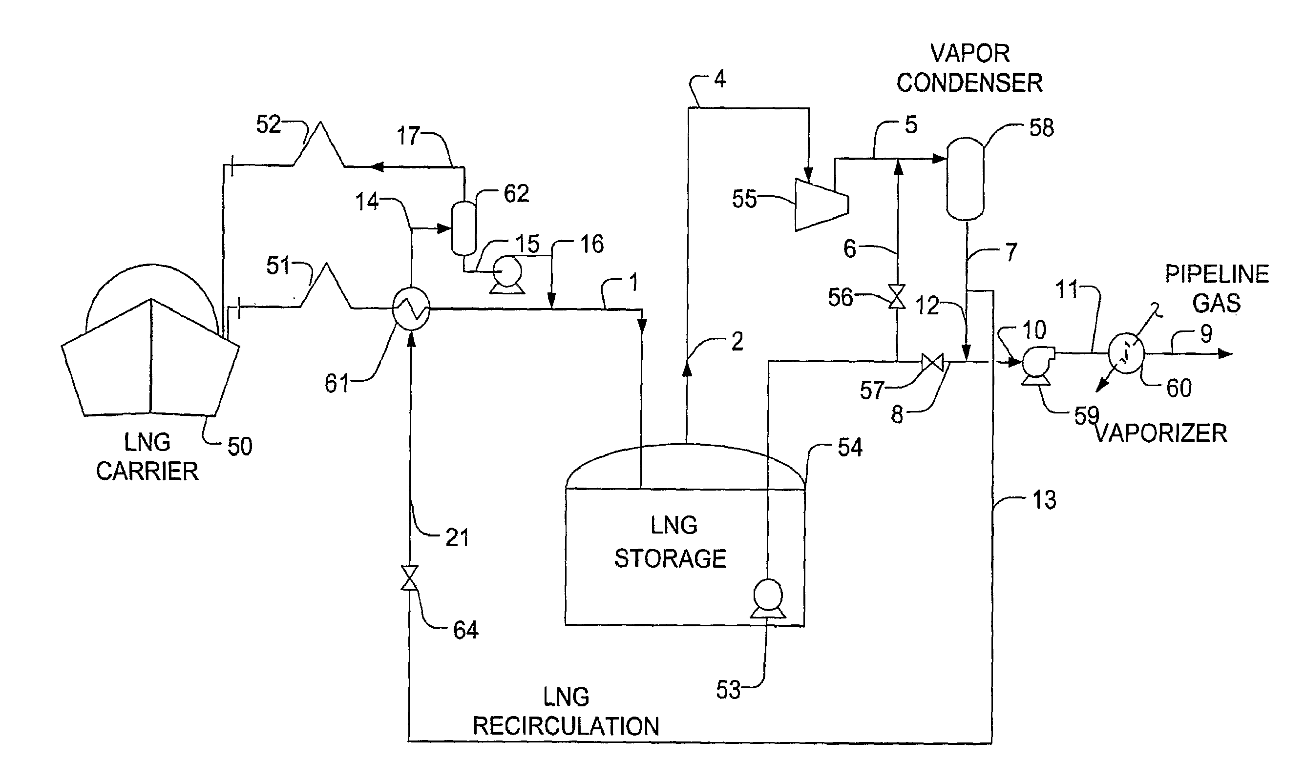
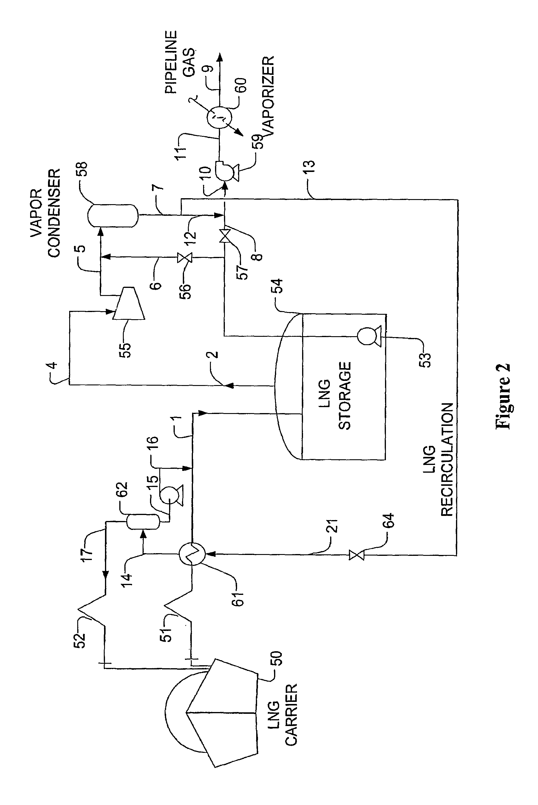
[0018]The present invention is directed to various configurations and methods for an LNG receiving terminal in which sendout LNG liquid from a storage tank is employed as refrigerant to subcool LNG that is being unloaded. Using such configurations, it should be noted that vapor generation from the tank is reduced to a significant degree and that the vapor return compressor and the return line to the LNG carriers of heretofore known configurations can be eliminated. It should still further be appreciated that the circulation line and pump system for the sendout LNG liquid can be advantageously used during normal holding operation, which will maintain the LNG transfer line at cryogenic temperature.

[0019]Most preferably, LNG is provided from an LNG carrier vessel or other remote source using conventional LNG transfer lines and one or more pumps to a conventional LNG storage tank that is fluidly coupled to a boil-off compressor and vapor condenser or absorber. The vapor condenser or abs...


PUM


Abstract

LNG from a carrier is unloaded to an LNG storage tank in configurations and methods in which expansion of compressed and condensed boil-off vapors from the LNG storage tank provide refrigeration to subcool the LNG that is being unloaded. Most advantageously, such configuration and methods reduce the amount of boil-off vapors and eliminate the need for a vapor return line and associated compressor.

Description

[0001]This application claims priority to our copending U.S. provisional patent application with the Ser. No. 60 / 792,196, which was filed Apr. 13, 2006.FIELD OF THE INVENTION[0002]The field of the invention is LNG vapor handling, and especially as it relates to vapor handling during LNG storage, ship unloading, and transfer operation.BACKGROUND OF THE INVENTION[0003]Despite its apparent simplicity, LNG ship unloading poses various significant challenges in several economic and technical aspects. For example, when LNG is unloaded from an LNG ship to a storage tank, LNG vapors are generated in the storage tank due to, among other factors, volumetric displacement, heat gain during LNG transfer and pumping, boil-off in the storage tank, and flashing (due to the pressure differential between the ship and the storage tank). In most cases, these vapors need to be recovered to avoid flaring and pressure buildup in the storage tank system.[0004]Moreover, LNG unloading docks and LNG storage t...

Claims


Application Information

Patent Timeline
IPC IPC(8): F17C7/02F17C7/04
CPCF17C6/00F17C2270/0136F17C2205/0364F17C2205/0367F17C2221/033F17C2223/0161F17C2223/0169F17C2223/033F17C2223/035F17C2223/046F17C2225/0123F17C2225/0161F17C2225/033F17C2227/0135F17C2227/0178F17C2227/0302F17C2227/0339F17C2227/0388F17C2227/0393F17C2260/023F17C2265/017F17C2265/032F17C2265/034F17C2265/037F17C2265/05F17C2270/0105F17C9/00
Inventor MAK, JOHN
Owner FLUOR TECH CORP
Why Eureka
Try Eureka