Resistance variable element

a variable element and resistance technology, applied in the field of resistance variable elements, can solve the problems of difficult optimum design of the reram, unfigured mechanism of operation,

Inactive Publication Date: 2009-09-03
NAGOYA INSTITUTE OF TECHNOLOGY +1
View PDF9 Cites 44 Cited by
  • Summary
  • Abstract
  • Description
  • Claims
  • Application Information

AI Technical Summary

Benefits of technology

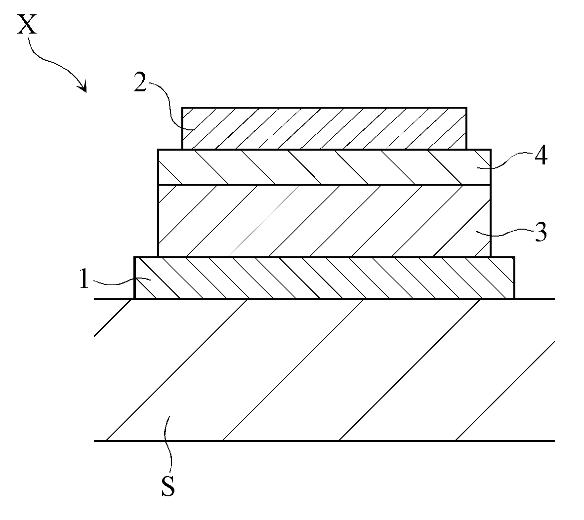
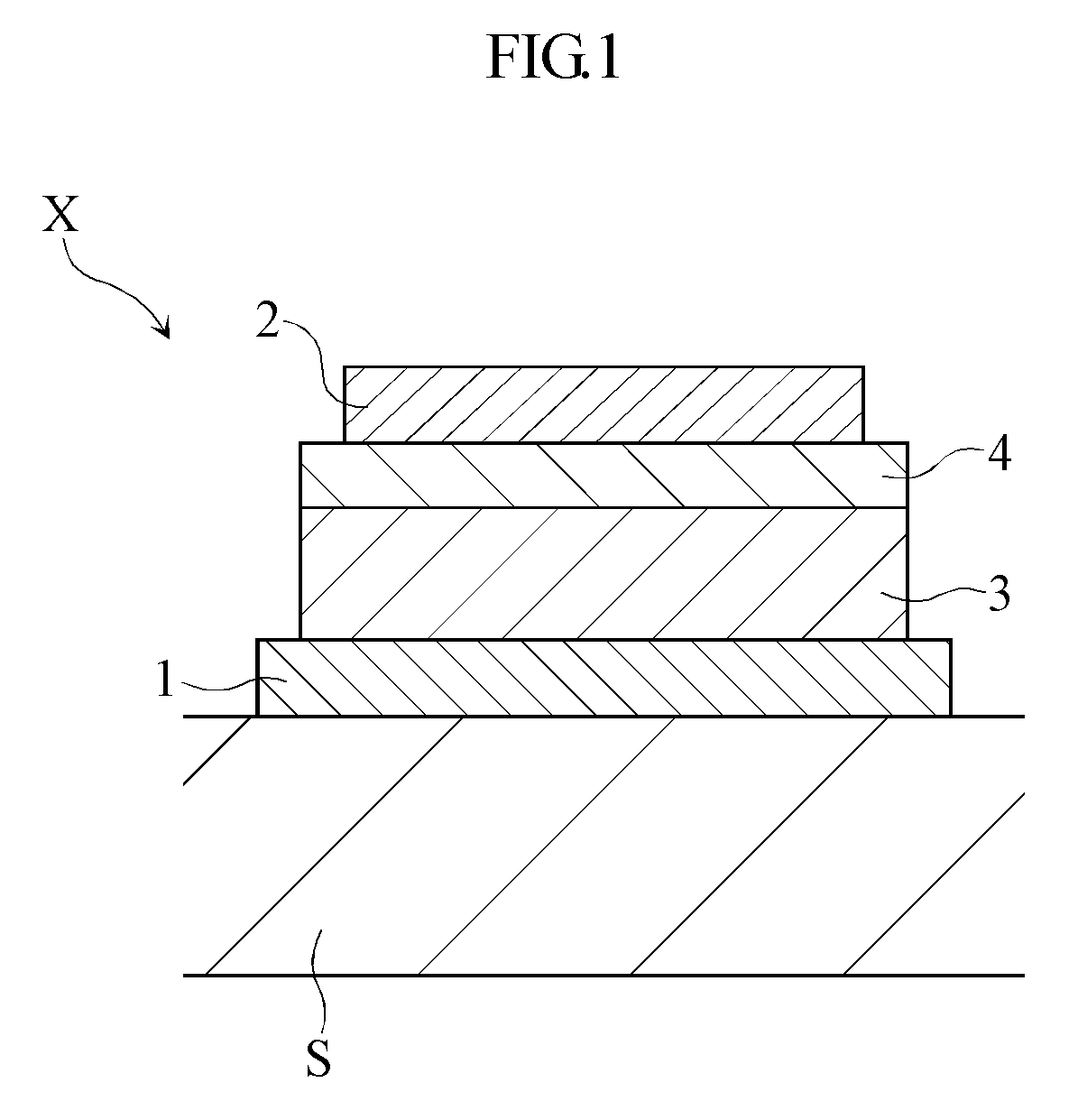
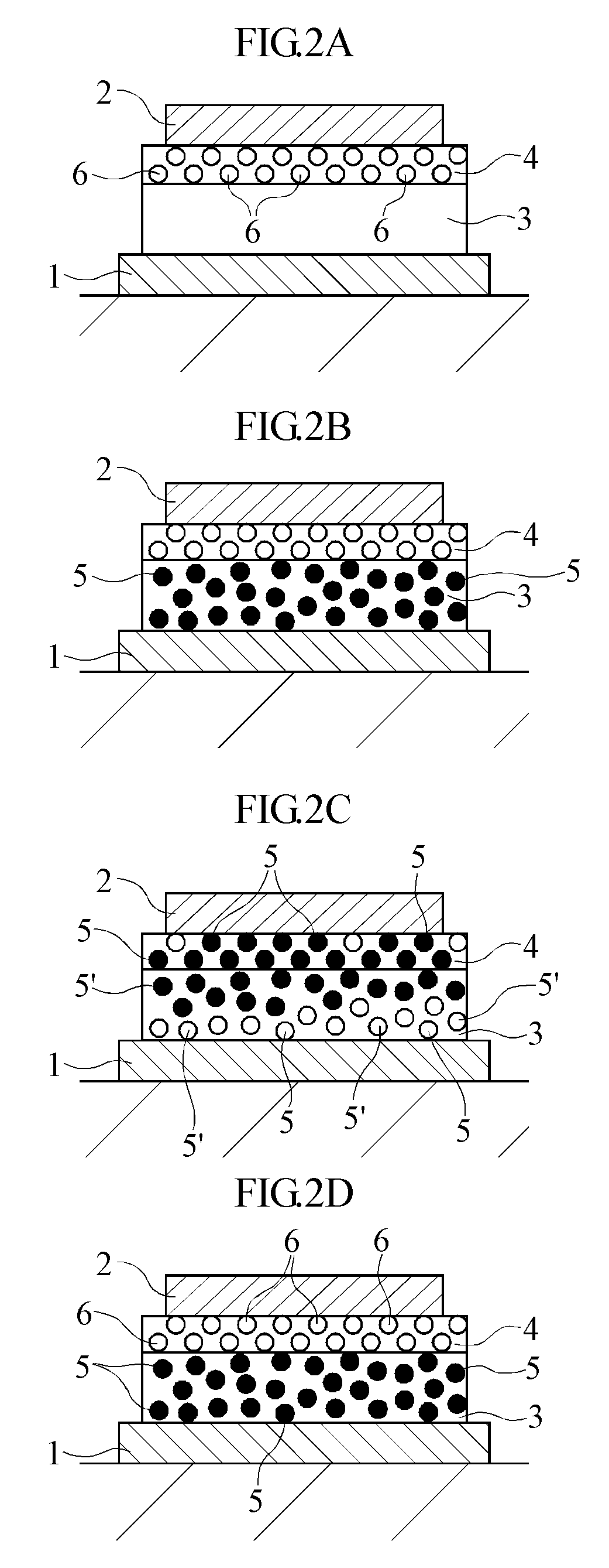
[0014]When a predetermined voltage is applied across the first and the second electrodes of this element in the low-resistance state with the first electrode and the second electrode held negative and positive, respectively, oxygen ions are generated in the first oxide layer and the oxygen ions move from the first oxide layer to the second oxide layer due to the electric field effect (i.e., donation of oxygen ions from the first oxide layer to the second oxide layer occurs). As a result, positive deficiencies (positively-charged oxygen vacancies in this case) are generated in the first oxide layer or the positive deficiencies in the first oxide layer increase. In the first oxide layer, the positive deficiencies are localized to a portion close to the first electrode. As a result, an internal electric field having an opposite polarity from the applied voltage is generated in the first oxide layer. The internal electric field hinders the movement of electrons or holes which are the main carriers in this element. Thus, due to the oxygen ion donation from the first oxide layer to the second oxide layer, the first oxide layer shifts from the low-resistance state to the high-resistance state. On the other hand, the second oxide layer is further oxidized (i.e., the degree of oxidation by oxygen increases) by accepting oxygen ions from the first oxide layer. The increase in the degree of oxidation hinders the movement of electrons or holes which are the main carriers in this element. Thus, by accepting oxygen ions from the first oxide layer, the second oxide layer shifts from the low-resistance state to the high-resistance state. In this way, since both of the first oxide layer and the second oxide layer shift from the low-resistance state to the high-resistance state, the element shifts from the low-resistance state to the high-resistance state. Even when the voltage is reduced, the first and the second oxide layers maintain the high-resistance state, so that the element maintains the high-resistance state.
[0018]Preferably, the first oxide layer and / or the second oxide layer is made of a conductive oxide. This arrangement is desirable for generating oxygen ions and oxygen vacancies without inducing breakage of a substance or structure between the two oxide layers due to dielectric breakdown and for reversibly moving the oxygen ions within each oxide layer and between the two oxide layers. Preferably, the activation energy of each oxide layer for the transfer of oxygen ions is not more than 2 eV.
[0019]Preferably, an alkaline earth element is added to the first oxide layer. Preferably, the first oxide layer and / or the second oxide layer is in an oxygen deficient state (the state in which a significant amount of oxygen vacancies which are free of electric charge exist). These arrangements are desirable for enhancing the conductivity of the first oxide layer and / or the second oxide layer, oxygen ion mobility of the first oxide layer and / or the second oxide layer and the readiness of transfer of oxygen ions between the two oxide layers. To accept oxygen ions inherent in the first oxide layer, an oxygen-deficient oxide is preferable as the material of the second oxide layer.
[0025]Preferably, the resistance variable element further includes an oxygen ion generation promoting layer held in contact with the first oxide layer and positioned between the first oxide layer and the first electrode. Preferably, the resistance variable element further includes an oxygen ion generation promoting layer held in contact with the second oxide layer and positioned between the second oxide layer and the second electrode. Preferably, the oxygen ion generation promoting layer is made of a conductive oxide containing a noble metal. These arrangements are desirable for efficiently generating oxygen ions in the element.

Problems solved by technology

However, although the fact that these ReRAMs are capable of performing bipolar operation is known, the mechanism of operation has not been figured out.
Since the mechanism of operation is unclear, the optimum material, dimension and so on of each part of the ReRAM cannot be determined, so that the optimum designing of the ReRAM is difficult.

Method used


Image

  • Resistance variable element
  • Resistance variable element
  • Resistance variable element

Examples


example

Sample Element S1

[0082]A sample element S1 having the laminated structure illustrated in FIG. 4A was prepared as a resistance variable element. The facing area of the electrodes 1 and 2 of the sample element S1 is 31400 μm2. (The facing area of the paired electrodes of each of the sample elements S2-S12, which will be described later, is also 31400 μm2.) In the initial state before voltage application, the sample element S1 was in the low-resistance state.

[0083]The change of the resistance of the sample element S1 was examined. Specifically, while measuring the resistance between the electrodes 1 and 2 of the sample element S1, voltage application under the first condition and that under the second condition were repetitively performed with respect to the sample element S1. Specifically, under the first condition, a pulse voltage with a pulse amplitude of 5V and a pulse width of 10 nsec was applied across the electrodes, with the electrode 1 and the electrode 2 held negative and pos...


PUM


Abstract

A resistance variable element is provided, which is capable of performing bipolar operation by a specified mechanism and usable as a memory. The resistance variable element has a laminated structure including an electrode, an electrode, an oxide layer between the electrodes, and an oxide layer in contact with the oxide layer between the oxide layer and the electrode. The oxide layer is switchable from the low-resistance state to the high-resistance state by donating oxygen ions to the oxide layer, and from the high-resistance state to the low-resistance state by accepting oxygen ions from the oxide layer. The oxide layer is switchable from the low-resistance state to the high-resistance state by accepting oxygen ions from the oxide layer, and from the high-resistance state to the low-resistance state by donating oxygen ions to the oxide layer.

Description

[0001]This application is a U.S. Continuation of International application No. PCT / JP2007 / 070117, filed Oct. 16, 2007.TECHNICAL FIELD[0002]The present invention relates to a resistance variable element which is switchable between a high-resistance state in which relatively small current flows and a low-resistant state in which relatively large current flows.BACKGROUND ART[0003]In the technical field of a nonvolatile memory, much attention is being focused on a ReRAM (resistive RAM). A ReRAM is a resistance variable element generally including a pair of electrodes and a recording film which is selectively switchable between a high-resistance state and a low-resistance state depending on the voltage applied between the paired electrodes. In the ReRAM, the selective switching of the resistance state of the recording film is utilized to record or rewrite information. Examples of such a ReRAM and resistance variable element are disclosed in Patent Documents 1-5 given below.[0004]Patent D...

Claims


Application Information

Patent Timeline
Patent Type & Authority Applications(United States)
IPC IPC(8): H01L29/02
CPCG11C13/0007G11C13/0069G11C2013/0073G11C2213/15G11C2213/31G11C2213/32H01L45/1625H01L27/101H01L45/08H01L45/1233H01L45/146H01L45/147G11C2213/56H10N70/24H10N70/8836H10N70/026H10N70/8833H10N70/826
Inventor KAWANO, HIROYASUSHONO, KEIJIGOMI, MANABUYOKOTA, TAKESHI
Owner NAGOYA INSTITUTE OF TECHNOLOGY
Why Eureka
Try Eureka