Windfarm collector system loss optimization

a technology of wind turbines and collectors, applied in the direction of electric generator control, machines/engines, mechanical equipment, etc., can solve the problems of wind turbine system development still, and achieve the effects of minimizing electrical loss, minimizing electrical loss, and minimizing electrical loss

Active Publication Date: 2009-09-03
GENERAL ELECTRIC CO
View PDF2 Cites 109 Cited by
  • Summary
  • Abstract
  • Description
  • Claims
  • Application Information

AI Technical Summary

Benefits of technology

[0012]The present invention relates to a windfarm system that is optimized for minimizing electrical loss and a method for minimizing electrical loss in the windfarm system.
[0013]Briefly in accordance with one aspect of the present invention, a windfarm system is provided that is optimized for minimizing electrical loss. The windfarm system includes a plurality of wind turbine generators and a collector system including a conductor or network of conductors. The collector system also includes a plurality of transformers with one or more transformers connected

Problems solved by technology

However, wind turbine system development is still in the early stages relative to competing technologies.
These alternatives

Method used


Image

  • Windfarm collector system loss optimization
  • Windfarm collector system loss optimization
  • Windfarm collector system loss optimization

Examples


Embodiment Construction

[0024]The following embodiments of the present invention have many advantages, including reducing windfarm power losses through optimization of reactive load distribution and system voltage control without a need for system hardware changes

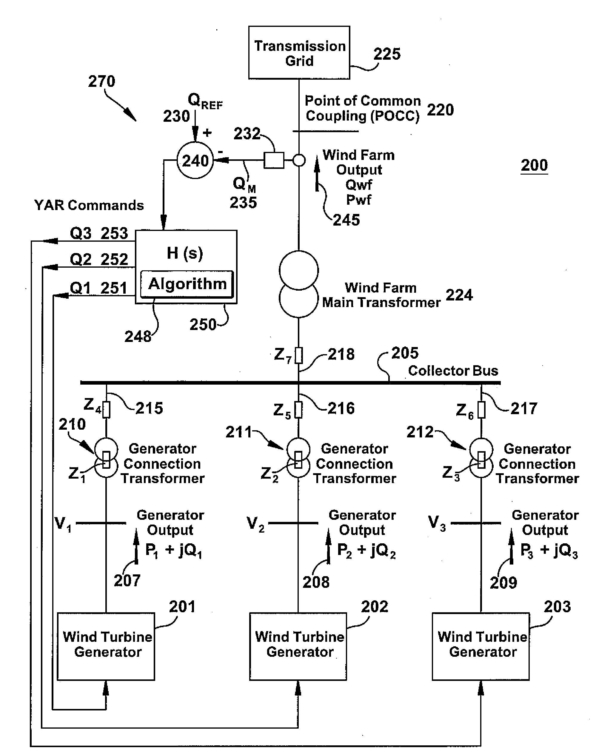
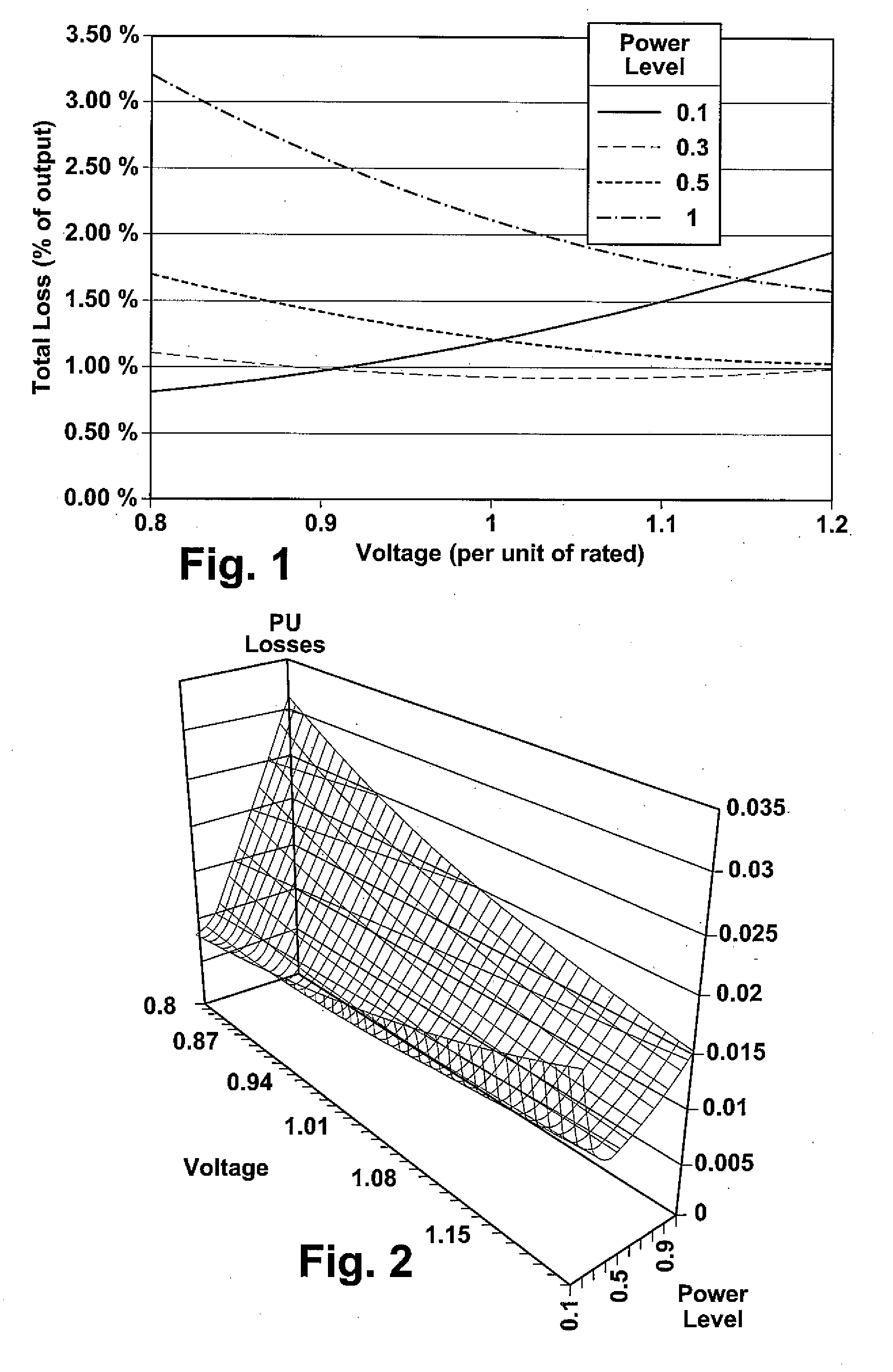
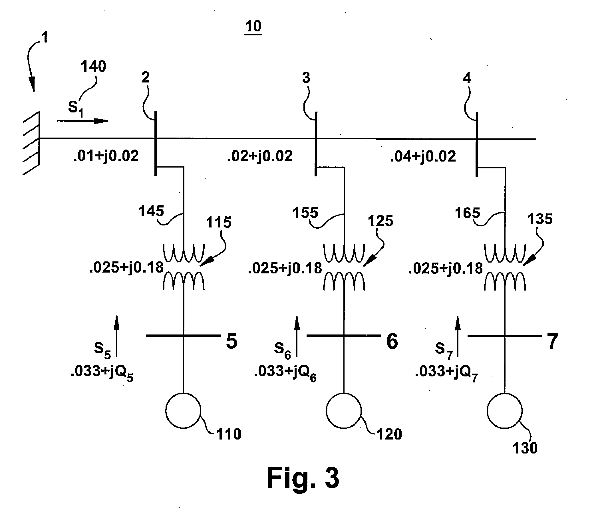
[0025]Currents flowing in a windfarm collector system create losses due to the electrical resistance of the system. A windfarm collector system is constructed as a long conductor with wind turbines connected in parallel along its length. The conductor may be in a simple radial configuration, in a dendritic topology with one or more branchings, or in a loop configuration. The wind turbine generators that are further away from the substation or point of common coupling transmit their power over a greater distance and thus exhibit more real and reactive power losses than turbines closer to the point of common coupling. Furthermore, current is inversely proportional to voltage for a constant power. By increasing collector system voltage, less current ...


PUM


Abstract

A windfarm system is provided that is optimized for minimizing electrical loss. The windfarm system includes a plurality of wind turbine generators and a collector system including a conductor or network of conductors. The collector system also including a plurality of transformers with one or more transformers connected between each wind turbine generator and the conductors, and a substation transformer connecting the windfarm collector system to the electrical grid. The windfarm system also includes a monitoring system for monitoring the windfarm system electrical output and thermal condition, and outputs of the individual wind turbine generators. A control function may include voltage and real and reactive power commands to the individual wind turbine generators. The control function incorporates an algorithm whose technical effect is minimizing electrical losses for the windfarm system.

Description

BACKGROUND OF THE INVENTION[0001]The invention relates generally to controlling power loss in a windfarm and more specifically to a system and method for distributing reactive load and windfarm voltage optimization for reduction of collector system losses.[0002]Wind turbines are anticipated to becoming a progressively larger source of energy throughout the world, based on their capture of a renewable source of energy that does not emit carbon-based gases. However, wind turbine system development is still in the early stages relative to competing technologies. More specifically, system control for groups of jointly controlled wind turbines, or wind farms, is still in its infancy.[0003]Current windfarm control techniques generally relate to voltage control and or real and reactive power control, either at the individual turbine or at a common collecting point for the system. Efficiency of the system, based on loss reduction, has generally not been considered in such control schemes.[0...

Claims


Application Information

Patent Timeline
IPC IPC(8): F03D9/00H02P9/04
CPCF03D7/028F03D7/048Y02E10/723F05B2270/1033F05B2240/96H02J3/16H02J2300/28H02J3/381Y02E10/76Y02E10/72Y02E40/30H02J3/50
Inventor CARDINAL, MARK E.DELMERICO, ROBERT W.MILLER, NICHOLAS W.WALLING, REIGH A.
Owner GENERAL ELECTRIC CO
Why Eureka
Try Eureka