Motor apparatus including lundell motor having lundell-type rotor

a motor and rotor technology, applied in the direction of rotating magnets, magnetic circuit rotating parts, synchronous machines with stationary armatures, etc., can solve the problems of low efficiency, low efficiency in high speed range, small output torque for body size, etc., to achieve rapid adjustment of output torque, high rotational speed, and large torque

Inactive Publication Date: 2009-09-03
DENSO CORP
View PDF13 Cites 29 Cited by
  • Summary
  • Abstract
  • Description
  • Claims
  • Application Information

AI Technical Summary

Benefits of technology

[0039]According to the present invention, there is provided a Lundell motor apparatus which can generate large torque per body size, and rapidly adjust output torque in a high rotational speed region.

Problems solved by technology

However, the above conventional IPM motor has a problem in that its efficiency is low in a high speed range, because a field-weakening control has to be performed in the high speed range.
Also, the SYRM has problems in that its output torque is small for its body size because the SYRM uses only the reluctance torque, and its efficiency is low because of the necessity to generate the d-axis flux.
However, the motor including a Lundell-type rotor has a problem in that its torque cannot be changed rapidly, because of the large inductance of its field coil.
In addition, the motor including a Lundell-type rotor has further problems in that the body size per output torque is large compared to the IPM motor, and its efficiency is low because of the necessity to pass a field current to the field coil.

Method used


Image

  • Motor apparatus including lundell motor having lundell-type rotor
  • Motor apparatus including lundell motor having lundell-type rotor
  • Motor apparatus including lundell motor having lundell-type rotor

Examples


first embodiment

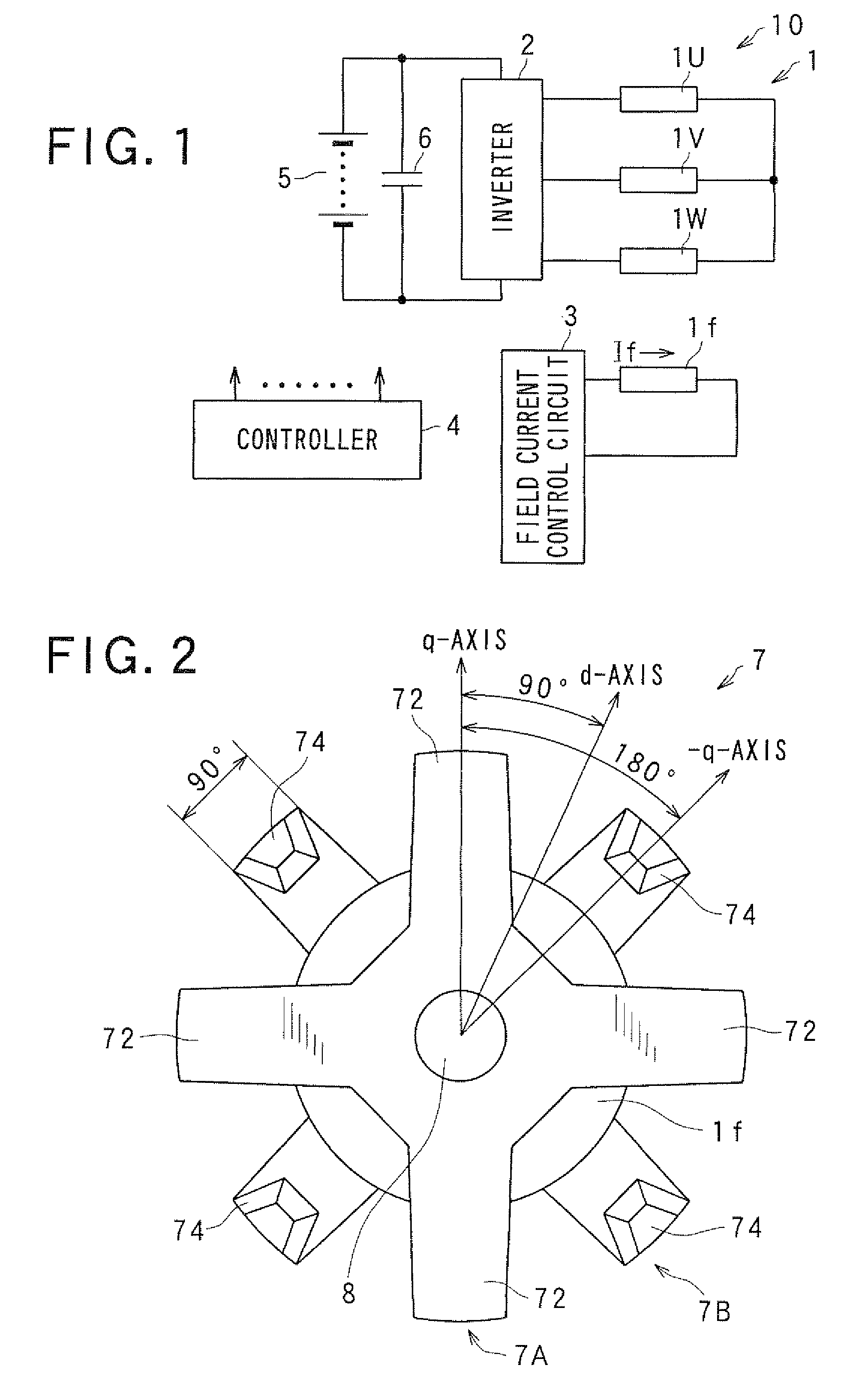
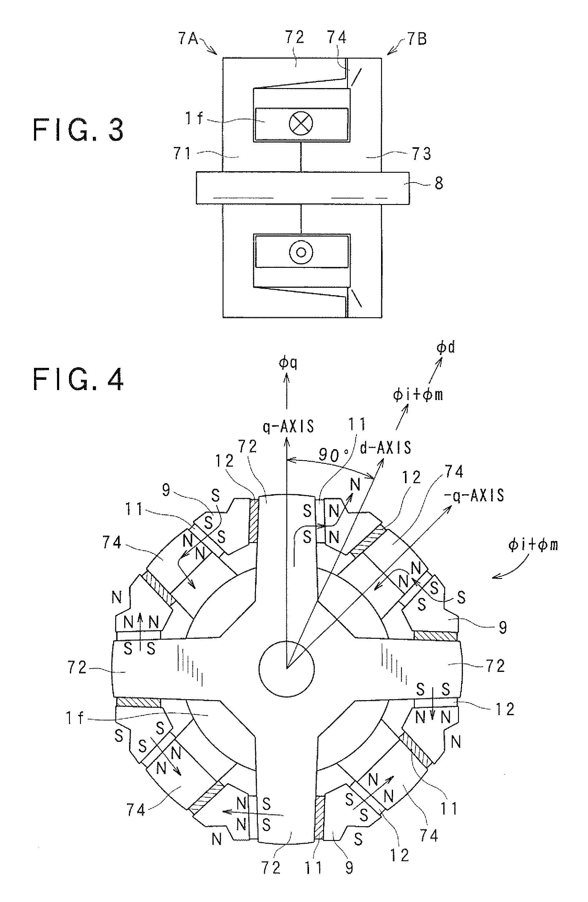
[0053]FIG. 1 is a circuit diagram of a motor apparatus including a motor having a Lundell-type rotor (may be referred to as “Lundell motor” hereinafter), FIG. 2 is an axial front view of a rotor of the Lundell motor, and FIG. 3 is an axial cross-sectional view of this rotor of the Lundell motor.

[0054]In FIG. 1, the reference numeral 1 denotes the Lundell motor, 2 denotes a three-phase inverter, 3 denotes a field current control circuit 3, 4 denotes a microcomputer-based controller for controlling the inverter 2 and the field current control circuit 3 on the basis of a torque command received from the outside, 5 denotes a vehicle battery, and 6 denotes a smoothing capacitor.

[0055]The Lundell motor 1 includes an armature coil (stator coil) 10 wound around a stator core (not shown), and a field coil 1f. The armature coil 10 is constituted of a U-phase coil 1U, a V-phase coil 1V and W-phase coil 1W which are star-connected to a common connection point. A field current If flowing through...

second embodiment

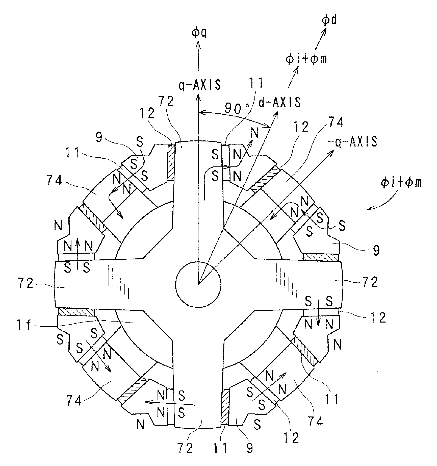
[0064]Next, a second embodiment of invention is described with reference to FIGS. 4 and 5. FIG. 4 is an axial front view of a rotor of a Lundell motor of the second embodiment, and FIG. 5 is an axial cross-sectional view of this rotor of the Lundell motor.

[0065]The second embodiment differs from the first embodiment in that it additionally includes a d-axis pole section 9 made of soft magnetic material, a tabular permanent magnet 11, and a non-magnetic metal plate 12, which are provided in each of the circumferential gaps between the claw pole sections 72 and the claw pole sections 74.

[0066]The claw pole sections 72 extend from the axial front side to the axial rear side, and the claw pole sections 74 extend from the axial rear side to the axial front side. The d-axis pole section 9 is located in the circumferential gap between the claw pole section 72 and the claw pole section 74 which are adjacent in the circumferential direction. The radial position of the radial end surface of t...

third embodiment

[0071]Next, a third embodiment of invention is explained with reference to FIGS. 6 and 7. FIG. 6 is an axial front view of a rotor of a Lundell motor of the third embodiment, and FIG. 7 is an axial cross-sectional view of this rotor of the Lundell motor.

[0072]The third embodiment differs from the second embodiment in that the non-magnetic plates 12 are replaced by tabular permanent magnets 13. As shown in FIG. 6, the permanent magnet 13 is magnetized in the opposite direction to the permanent magnet 11 which is across the d-axis pole section 9 from this permanent magnet 13, or in the same direction as the permanent magnet 11 which is across the claw pole section 72 or 74 from this permanent magnet 13.

[0073]In the Lundell motor of this embodiment having the above described structure, most of the field flux generated by the field current If flowing through the field coil 1f and entering the claw pole section 72 through the boss section 71 is bent from the side of the radial outer end ...


PUM


Abstract

The Lundell motor apparatus includes a controller for controlling a field current passed to a field coil of a Lundell-type rotor of a motor and an armature current passed to a stator coil of the motor in order to generate a required torque. When the field current is If, the armature current is Ia, a d-axis inductance is Ld, a q-axis inductance is Lq, a q-axis current as a q-axis component of the armature current is Iq, a d-axis current as a d-axis component of the armature current is Id, a field torque is Tf, a field flux is Φf, a reluctance torque is Tr, and a combined torque of the field torque and the reluctance torque is ΣT, the controller passes the d-axis current Id to the stator coil within a phase angle range in which the combined torque ΣT become larger than the field torque Tf in order to generate the reluctance torque Tr which is equal to (Ld−Lq)Id·Iq in addition to the field torque Tf.

Description

CROSS-REFERENCE TO RELATED APPLICATION[0001]This application is related to Japanese Patent Application No. 2008-49833 filed on Feb. 29, 2008, the contents of which are hereby incorporated by reference.BACKGROUND OF THE INVENTION[0002]1. Field of the Invention[0003]The present invention relates to a motor apparatus including a Lundell motor having a Lundell-type rotor.[0004]2. Description of Related Art[0005]Lundell-type rotors are widely used for vehicle alternators required to be capable of adjusting power generation voltage thereof by controlling a field current. The Lundell-type rotors have a structure including a rotor core constituted by a cylindrical boss section and a plurality of claw-poles which extend from both axial end surfaces of the boss section radially outward at a predetermined circumferential pitch, and then extend in the axial direction such that the claw-poles extending from one of the end surfaces alternate with the opposed claw-poles extending from the other en...

Claims


Application Information

Patent Timeline
Patent Type & Authority Applications(United States)
IPC IPC(8): H02K1/27H02K19/22H02K21/14
CPCH02K21/044
Inventor KUSASE, SHIN
Owner DENSO CORP
Why Eureka
Try Eureka